MOSFET circuit structure for motor controller of battery electric vehicle

A motor controller, pure electric vehicle technology, applied in circuits, circuit thermal devices, electric solid devices, etc., can solve the problems of large heat dissipation space, large occupation, limited electric vehicle space, etc., and achieve the effect of large heat dissipation space

Inactive Publication Date: 2018-05-15
SHENZHEN HOHOMER DIGITAL POWER TECH CO LTD
View PDF4 Cites 2 Cited by
  • Summary
  • Abstract
  • Description
  • Claims
  • Application Information

AI Technical Summary

Problems solved by technology

The existing MOSFET circuit structure will occupy a large space because the control PCB board and the driving PCB board are installed separately, and the driving

Method used


Image

  • MOSFET circuit structure for motor controller of battery electric vehicle

Examples


Embodiment Construction

[0014] The present invention will be described in further detail below in conjunction with the embodiments and with reference to the accompanying drawings.

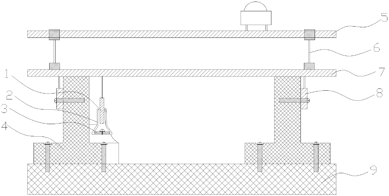
[0015] For the MOSFET circuit structure of a pure electric vehicle motor controller in this embodiment, please refer to the attached figure 1 , including a control PCB board 5 and a driving PCB board 7, the control PCB board 5 is suspended above the driving PCB board 7 by using at least three pin headers 6, and at least two rows of power tubes are flip-mounted on the lower surface of the driving PCB board 7 8. The heat dissipation surface of each row of power tubes 8 is installed on the side of the heat conduction block 4 , and the bottom of the heat conduction block 4 is installed on the heat dissipation bottom plate 9 .

[0016] In this structure, the control PCB board 5 is suspended above the driving PCB board 7 by using at least three row pins 6, and at least two rows of power tubes 8 are inverted on the lower surface...


PUM


Abstract

The invention discloses a MOSFET circuit structure for a motor controller of a battery electric vehicle. The MOSFET circuit structure comprises a control PCB and a driving PCB, wherein the control PCBis suspended above the driving PCB by virtue of at least three pin headers, at least two rows of power pipes are inversely mounted on the lower surface of the driving PCB board, the heat dissipationsurfaces of each row of power pipes are mounted on the side surface of a heat conduction block, and the bottom of the heat conduction block is mounted on a heat dissipation base plate. The MOSFET circuit structure has the advantages that the utilized space is small, and the heat dissipation effect is good.

Description

technical field [0001] The invention relates to a circuit structure, in particular to a MOSFET circuit structure with less space utilization and good heat dissipation effect for a pure electric vehicle motor controller. Background technique [0002] In the actual work of the battery protection board of electric vehicles, according to different applications, multiple power transistors (power MOSFETs) will be used to work in parallel to reduce the on-resistance and enhance the heat dissipation performance. The existing MOSFET circuit structure will occupy a large space because the control PCB board and the driving PCB board are installed separately, and the driving PCB board installed with the power tube needs a large space for heat dissipation, and the space of the electric vehicle is limited. It caused a certain contradiction. Contents of the invention [0003] In order to solve the above problems, the object of the present invention is to provide a MOSFET circuit structu...

Claims


Application Information

Patent Timeline
IPC IPC(8): H01L23/367H05K1/02
CPCH01L23/367H05K1/0204
Inventor 余得贵闫伟伟
Owner SHENZHEN HOHOMER DIGITAL POWER TECH CO LTD
Why Eureka
Try Eureka