LCOS optical projection system

An optical projection and spectroscopic technology, used in optics, optical components, instruments, etc., can solve the problems of many components, high manufacturing cost, complex structure, etc., and achieve the effect of less optical components, reduced weight, and high resolution

Active Publication Date: 2006-01-25
SHENZHEN KECHUANG DIGITAL DISPLAY TECH
View PDF0 Cites 5 Cited by
  • Summary
  • Abstract
  • Description
  • Claims
  • Application Information

AI Technical Summary

Problems solved by technology

[0003] The purpose of the present invention is to provide a LCOS optical projection system that can meet the requirements of high definition, low manufacturing cost, and miniaturization, so as to overcome the complex structure, many parts, large volume and heavy weight of the existing transmissive liquid crystal projection system. , High manufacturing cost and other disadvantages

Method used


Image

  • LCOS optical projection system
  • LCOS optical projection system
  • LCOS optical projection system

Examples


Embodiment 1

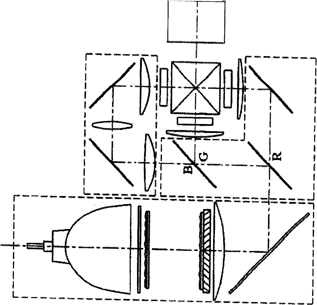
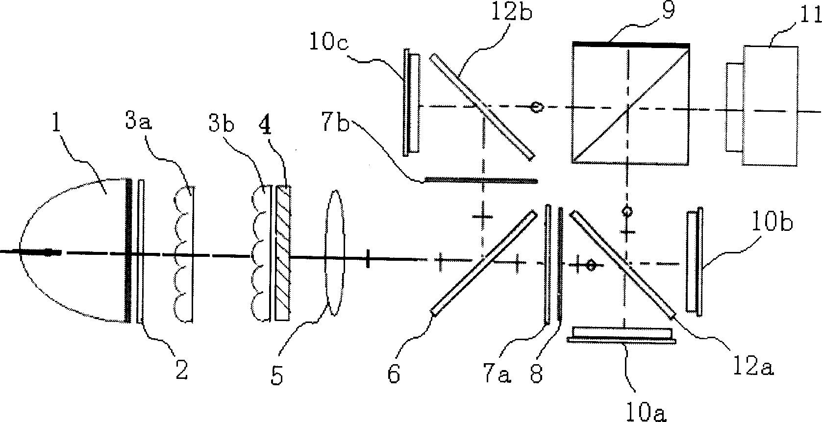
[0021] Embodiment 1: as image 3 As shown, it includes an illumination source 1, an ultraviolet and an infrared filter 2, two lens arrays 3 (respectively marked as 3a and 3b), a polarization conversion system 4, a condenser lens 5, a beam splitter 6, and two polarizers 7 ( respectively marked as 7a and 7b), wavelength selective deflector 8, light-combining prism 9, three reflective imaging components 10 (respectively marked as 10a, 10b and 10c), and can receive the imaging light converged by light-combining prism 9 Projection objective lens 11; illuminating light source 1, ultraviolet and infrared filter 2, two lens arrays 3 and polarization conversion system 4, located in turn on one side of the optical axis of the condenser lens 5, and perpendicular to the optical axis of the condenser lens 5; The beam splitter 6 is located on the focal plane of the other side of the condenser lens 5, and forms an angle of 45° with the optical axis of the condenser lens 5; a polarizer 7a, a ...

Embodiment 2

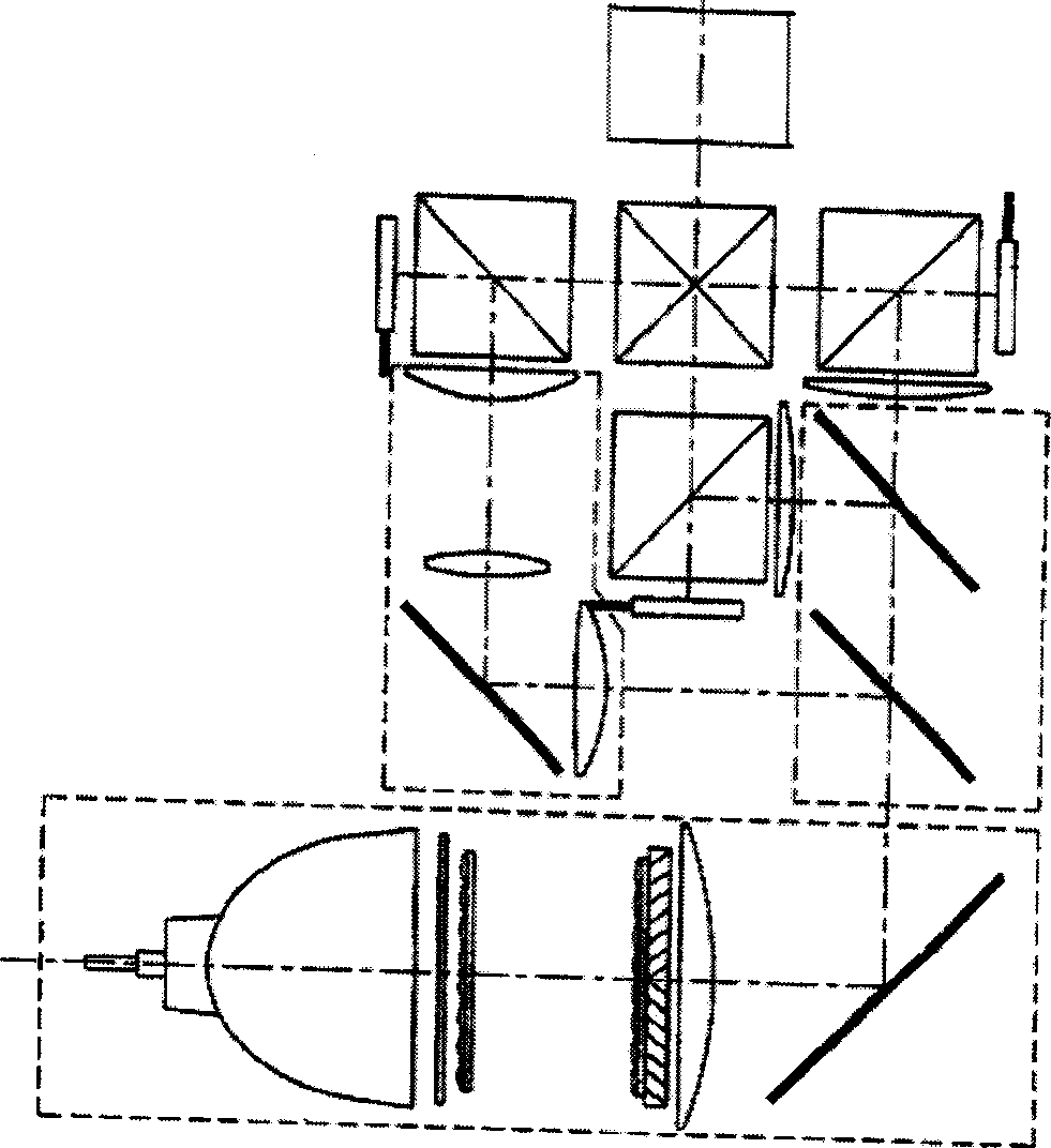
[0029] Embodiment 2: as Figure 4 As shown, the structure of the LCOS optical projection system in the present embodiment is partly the same as in Embodiment 1, the difference is that a polarizer 7a is vertically positioned on the straight line where the optical axis of the condenser lens 5 passes through the beam splitter plate 6. The polarizing plate is provided with a reflective imaging component 10a on one side away from the beam splitter plate 6, and the reflective imaging component is parallel to the optical axis of the condenser lens 5 and passes through the straight line of the beam splitter plate 6; On the straight line after the reflection of the flat plate 6, another polarizing plate 7b perpendicular to the straight line, a wavelength selective deflector 8 and a reflective imaging component 10c are arranged successively, and the described wavelength selective deflector 8 is attached on the polarizing plate 7b; Between the wavelength selective deflector 8 and the ref...


PUM


Abstract

The invention discloses a LCOS optical projecting system, comprising illuminating light source, ultraviolet and infrared filter, two lens arrays, polarization converting system, projection lens, beam splitter plate, two polarizing plates, wavelength selective deflector, three reflecting imaging component, beam merging prism and projection lens, as well as two reflective polarizers, and the beam merging prism is arranged in the position able to receive the lights the reflecting polarizer transmits and reflects.

Description

technical field [0001] The invention relates to an optical imaging system, in particular to an LCOS optical projection system of a rear projection TV. technical background [0002] The optical-mechanical structures currently used in projectors and rear-projection systems all use a small panel to form an image, and then irradiate the panel with light to enlarge it through the lens. Current projection systems can be broadly classified into two types, transmissive and reflective, according to the number of imaging panels used. The illumination system and spectroscopic system of these two systems are roughly the same, including light sources, ultraviolet and infrared filters, lens arrays, polarization conversion systems, and condenser lenses. Commonly used transmissive three-chip LCD systems such as figure 1 As shown; the commonly used reflective three-chip LCD system structure is as follows figure 2 As shown, it divides white light into three basic colors through a spectros...

Claims


Application Information

Patent Timeline
Patent Type & Authority Applications(China)
IPC IPC(8): G02B27/18G02F1/133
Inventor 李方红汤波周立
Owner SHENZHEN KECHUANG DIGITAL DISPLAY TECH
Why Eureka
Try Eureka