Injection mold

A technology of injection mold and injection cavity, which is applied in the field of injection mold, can solve the problems of reducing injection molding efficiency, producing quality defects, and the pressure of injection molding machine cannot be transmitted uniformly and quickly, so as to improve injection molding efficiency and ensure product quality.

Inactive Publication Date: 2018-05-18
KA FUNG IND TECH HUIZHOU CO LTD
View PDF3 Cites 2 Cited by
  • Summary
  • Abstract
  • Description
  • Claims
  • Application Information

AI Technical Summary

Problems solved by technology

The material flow during injection molding is mainly realized by the injection pressure of the injection molding machine and the fluidity of the fluid itself. When the injection molding cavity is large or long, the pressure of the injection molding machine cannot be transmitted uniformly and quickly, which not only reduces the injection molding efficiency, but also affects the molding density of the product. , resulting in quality defects

Method used


Image

  • Injection mold
  • Injection mold

Examples


Embodiment Construction

[0011] The present invention will be further described in detail below in conjunction with the embodiments and drawings, which are only for explanation and not intended to limit the protection scope of the present invention.

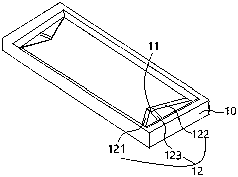
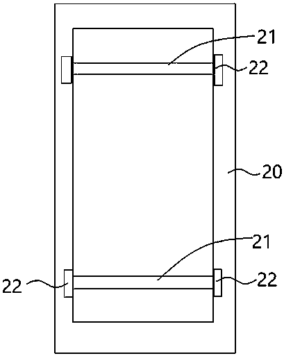
[0012] as attached figure 1 As shown in ~2, the injection mold described in this embodiment is composed of an upper mold 10 and a lower mold 20. The upper mold 10 is provided with a glue filling port 11, and the glue filling mouth 11 penetrates the entire upper mold from the opening on the upper surface of the upper mold. The glue port is connected with a plurality of diversion grooves 12 at the exit of the lower surface of the upper mold, and the diversion grooves 12 extend from the glue filling port on the inner surface of the upper mold to the cavity of the lower mold corresponding to the shape and size of the part to be injected.

[0013] In this embodiment, the cavity to be injected of the lower mold is a relatively long rectangular structure, and ...


PUM


Abstract

The invention relates to an injection mold. The injection mold comprises an upper mold and a lower mold; the upper mold is provided with a glue filling port and guide grooves communicating with the glue filling port; the lower mold is provided with an injection molding cavity corresponding to parts to be molded in shape; multiple guide grooves are provided; one ends of all the guide grooves are connected with the glue filling port, and the other ends are uniformly distributed on the long edges of the injection molding cavity of the lower mold, so that injection molding materials entering the glue filling port are uniformly dispersed through the guide grooves to flow into the molding cavity of the lower mold; and the guide grooves at least comprise first guide grooves and second guide grooves whose other ends are connected with the two ends of the injection molding cavity of the lower mold. The mold is provided with multiple guide grooves; molten materials injected from the glue fillingport are guided into the molding cavity to be injected through the multiple guide grooves; and the multiple guide grooves can transfer the pressure of an injection molding machine better and quickly,so that the molten materials can be uniformly and stably guided into the molding cavity, the injection molding efficiency is improved, and the product quality is guaranteed.

Description

technical field [0001] The invention relates to an injection mold. Background technique [0002] Injection molding is a method for the production of industrial products. Generally, injection molding machines are used to make thermoplastic or thermosetting materials into various shapes of plastic products using plastic molding molds. When injection molding, a mold with a specific shape is firstly prepared, and the glue filling port is set on the mold. The molten material is injected into the glue filling port through the pressure of the injection molding machine, and then flows into the set cavity through the diversion channel to solidify and form. The material flow during injection molding is mainly realized by the injection pressure of the injection molding machine and the fluidity of the fluid itself. When the injection molding cavity is large or long, the pressure of the injection molding machine cannot be transmitted uniformly and quickly, which not only reduces the inje...

Claims


Application Information

Patent Timeline
Patent Type & Authority Applications(China)
IPC IPC(8): B29C45/27
CPCB29C45/27
Inventor 李远发黄永铨刘建平刘军蒋成黄维中蔡忠祥宋卓能
Owner KA FUNG IND TECH HUIZHOU CO LTD
Why Eureka
Try Eureka