
A pipe cleaning robot

A technology of robot and robot body, applied in the field of robotics, can solve the problems of tree root removal, manual cleaning of debris that cannot be firmed, etc.

Active Publication Date: 2019-10-01
HOHAI UNIV CHANGZHOU
View PDF4 Cites 0 Cited by
  • Summary
  • Abstract
  • Description
  • Claims
  • Application Information

AI Technical Summary

Problems solved by technology

[0008] The present invention provides a pipeline cleaning robot in order to solve the problem that manual cleaning is required in the pipeline dredging and cleaning process in the prior art and firm debris such as tough tree roots cannot be removed.

Method used


Image

  • A pipe cleaning robot
  • A pipe cleaning robot
  • A pipe cleaning robot

Examples


Embodiment Construction

[0032] The present invention will be further explained in detail below in conjunction with the accompanying drawings and specific embodiments, but it should be understood that the protection scope of the present invention is not limited by the specific embodiments.

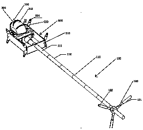
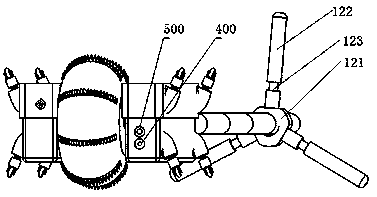
[0033] Such as figure 1 and figure 2 As shown, a pipe cleaning device in the present invention includes a semi-automatic manual propulsion device 100 and a robot body connected to the propulsion device 100. The robot body includes a grinding device 300, a flushing device, a lighting device 500, a visual device 400, a waterproof Fuselage, traveling mechanism 200, transmission device.

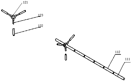
[0034] Such as image 3 As shown, the propulsion device 100 is composed of a splicable propulsion rod 110 and a chuck fixing device 120 . The splicable propulsion rod 110 is formed by connecting a plurality of rod bodies of the same specification, the number of required connecting rods 123 can be determined according to the lengt...


PUM


Abstract

The invention relates to a pipeline cleaning robot. The robot comprises a propulsion device and a robot body, the propulsion device comprises a propulsion rod formed by a plurality of freely-detachable rod bodies, and one end of the propulsion rod is connected with the robot body; the robot body comprises a walking mechanism, a grinding device and a flushing device, and the grinding device is installed on the walking mechanism; the walking mechanism comprises a vehicle frame, and universal wheels arranged in the circumference of the vehicle frame, the universal wheels are in contact with the side wall of a pipeline, the grinding device comprises rolling wheels and serrated cutters fixed on the side walls of the rolling wheels, the rolling wheels are rotatably connected with the vehicle frame, the propulsion device is connected with the grinding device through the vehicle frame, the flushing device is used for flushing out wastes ground by the grinding device, and the flushing device comprises a high-pressure water jet. The robot is capable of achieving thorough cleaning of the pipeline.

Description

technical field [0001] The invention relates to a robot, in particular to a pipeline cleaning robot for cleaning sundries in pipelines. Background technique [0002] The rainwater pipeline is a very important link in the urban drainage system. In the rainwater pipeline, the diameter of the main pipeline can be cleaned. What needs to be solved is the cleaning of the branch pipeline network. The diameter of the branch pipeline is small, and it is difficult for manual or cleaning tools to enter, and for No-pressure pipelines rely on the slope of the pipeline design and the discharge of rainwater itself, which is easy to deposit sediment, construction waste, plant debris, etc. In addition, the roots of trees on the surface are easy to extend into the pipeline, and the situation of pipeline blockage is very easy to occur. Cement accumulation in the pipeline reduces drainage area, tree roots are coiled to block solid waste, and finally several kinds of waste and silt form obstacle...

Claims


Application Information

Patent Timeline
Patent Type & Authority Patents(China)
IPC IPC(8): E03F9/00
Inventor 赵春王延杰赵苏雅朱灯林骆敏舟
Owner HOHAI UNIV CHANGZHOU
Learn More