Phase change heat storage device based on condensation heat transfer and its key parameter determination method

A technology of phase change heat storage and heat transfer coefficient, which is applied in complex mathematical operations, cooling/ventilation/heating transformation, modification with liquid cooling, etc., can solve problems such as inability to match the heat storage needs of gas-liquid mixed refrigerants, and achieve The effect of enhanced heat conduction process, enhanced condensation heat transfer process, and smooth operation

Active Publication Date: 2021-09-21
NANJING UNIV OF SCI & TECH
View PDF18 Cites 0 Cited by
  • Summary
  • Abstract
  • Description
  • Claims
  • Application Information

AI Technical Summary

Problems solved by technology

Among the current phase change heat storage devices, such as the phase change heat storage device of patent No. 201720508512.8, only the input conditions of the liquid phase refrigerant are considered, and it cannot match the heat storage requirements when the gas-liquid mixed refrigerant is input.

Method used


Image

  • Phase change heat storage device based on condensation heat transfer and its key parameter determination method
  • Phase change heat storage device based on condensation heat transfer and its key parameter determination method
  • Phase change heat storage device based on condensation heat transfer and its key parameter determination method

Examples


Embodiment

[0119] This embodiment is implemented on the premise of the technical solution of the present invention, and provides a detailed implementation manner and a specific operation process, but the protection scope of the present invention is not limited to the following embodiments.

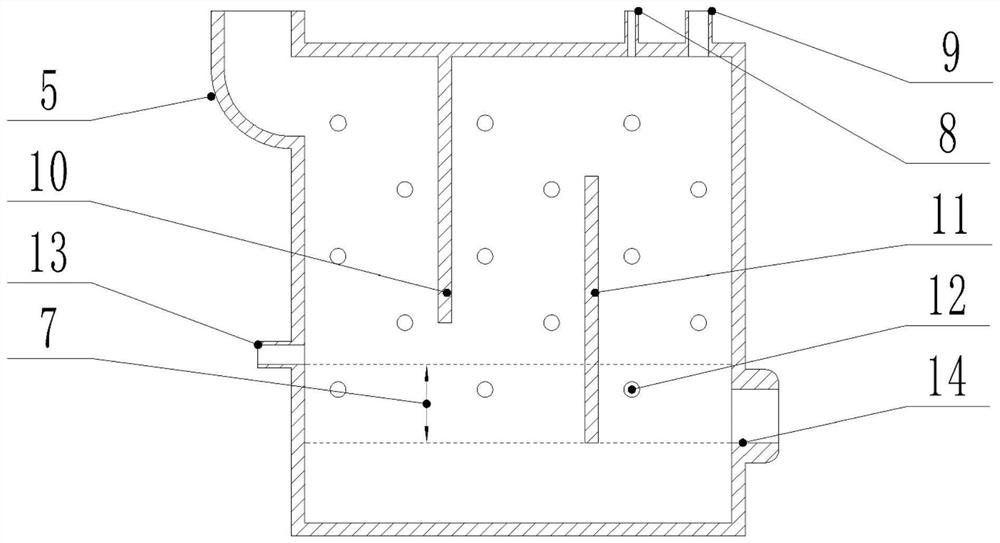
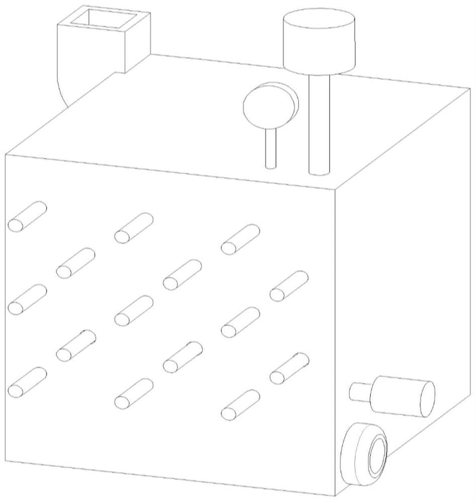
[0120] The design condition is a thermal load peak of 300kW for 6s with 100s interval. The input temperature of the steam inlet 5 is 10°C, and the input temperature of the inner heat exchange tube 1 is -25°C.

[0121] According to the above calculation steps, the parameter calculation of the phase change heat storage device is performed.

[0122] Step 1. Estimate and round to obtain the condensation point T of the phase change heat storage device 3 -10℃, phase transition point T 4 is -15℃;

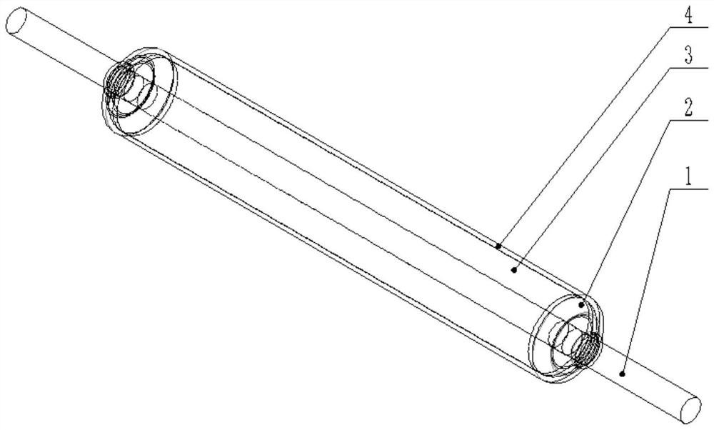
[0123] Step 2. Select the outer diameter d of the inner heat exchange tube 1 2 is 3mm, the calculated wall thickness t 1 is 0.25mm;

[0124] Step 3. It is calculated that the volume V of the phase change he...


PUM


Abstract

The invention proposes a phase change heat storage device based on convective heat exchange and a method for determining key parameters thereof. The device includes a condensation sleeve and a shell of the phase change heat storage device; the shell of the phase change heat storage device is provided with a steam inlet, a condensation jacket Pipe interface, overflow valve and condensate pump; the steam inlet is located at the top corner of the shell of the phase change heat storage device; the condensate pump is located at the bottom corner opposite to the steam inlet; at least one set of The first steam channel plate and the second steam channel plate; the steam channel plate, the steam channel plate and the condensate level divide the inner cavity of the shell of the phase change heat storage device into a plurality of wave-shaped steam condensation channels; multiple condensation sleeves pass through The condensing sleeve interface is inserted in the shell of the phase change heat storage device; the axial direction of the condensing sleeve is parallel to the first steam channel plate; the condensing sleeve in each steam condensing channel is arranged in a wave shape along the height direction. The final design of the phase change heat storage device can be obtained through the parameter determination method, which reduces the demand for heat dissipation capacity.

Description

technical field [0001] The invention belongs to the field of phase change heat storage, in particular to a phase change heat storage device based on condensation heat transfer and a method for determining key parameters thereof. Background technique [0002] For the heat dissipation problem of high-power electronic equipment, due to the high heat flux density on its surface, it can reach 100W / cm 2 ~1000W / cm 2 , the heat transfer enhancement method of microchannel flow is often used to improve the surface heat transfer capability, such as the microchannel evaporator of Patent No. 201910591725.5. Due to the large flow resistance in the microchannel, in order to reduce the design requirements of the circulating water pump, it is necessary to increase the heat dissipation per unit volume of refrigerant, and boiling the input liquid refrigerant is a common method to increase the heat dissipation per unit volume of the refrigerant. [0003] The heat dissipation process of electr...

Claims


Application Information

Patent Timeline
Patent Type & Authority Patents(China)
IPC IPC(8): H05K7/20G06F17/18
CPCG06F17/18H05K7/20H05K7/20309H05K7/20318H05K7/20336
Inventor 李强林肯胡定华
Owner NANJING UNIV OF SCI & TECH
Why Eureka
Try Eureka