Pressure reducing valve

A pressure reducing valve and valve body technology, applied in the direction of safety valves, balance valves, valve devices, etc., can solve problems such as incomplete completion, multiple pressure reducing valve components, low output pressure, etc., to improve the pressure reducing accuracy and prolong the service life , the effect of easy installation

Pending Publication Date: 2018-05-18
徐州青枣节能科技有限公司
View PDF5 Cites 3 Cited by
  • Summary
  • Abstract
  • Description
  • Claims
  • Application Information

AI Technical Summary

Problems solved by technology

[0003] 1. Problems such as corrosion, deformation and fracture caused by the long-term use of the compression spring directly affect the performance and service life of the main body product
[0004] 2. The unique adsorption of the sealing ring directly affects the working accuracy of the pressure reducing valve
When the pressure reducing valve is in a static state for a long time, its internal sealing ring will be adsorbed on the fittings that are sealed with it, which will produce uneven resistance to the movement of the fittings. The longer the static time, the greater the relative resistance, resulting in insensitive movement of the fittings. Directly affect the working accuracy of the pressure reducing valve
[0005] 3. Due to the shortcomings of the pressure spring and sealing ring accessories that are indispensable to the pressure reducing valve of the traditional structure, it is impossible to complete the pressure reducing valve with lower output pressure and the more stable low pressure pressure reducing valve
At the same time, the traditional pressure reducing valve has many components and complex structure.

Method used


Image

  • Pressure reducing valve
  • Pressure reducing valve
  • Pressure reducing valve

Examples


Embodiment Construction

[0031] Below in conjunction with embodiment the present invention is further described.

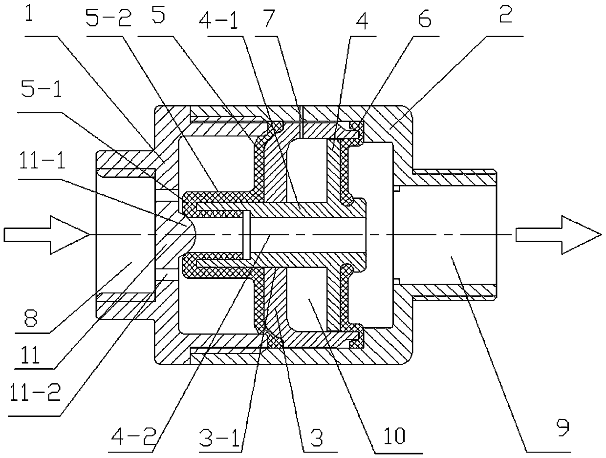
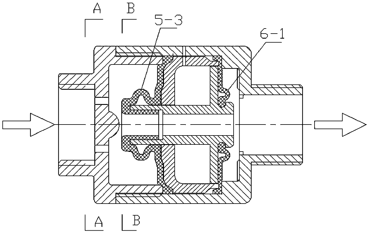
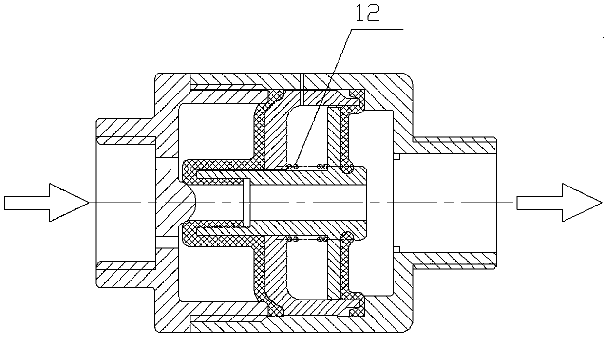
[0032] as attached Figure 1-Figure 5 A pressure reducing valve shown includes a valve body, one end of the valve body is a high-pressure chamber 8 connected to a high-pressure pipeline, and the other end of the valve body is a low-pressure chamber 9 connected to a downstream pipeline. The cavity is equipped with a support sleeve 3, which divides the inner cavity of the valve body into a high-pressure half area connected with the high-pressure chamber 8 and a low-pressure half area communicated with the low-pressure chamber 9, and the end of the support sleeve 3 facing the high-pressure chamber 8 is a closed end , the end of the support sleeve 3 facing the low-pressure chamber 9 is an open end;

[0033] The supporting sleeve 3 is equipped with a piston 4 that can slide axially in the inner cavity 10 of the supporting sleeve. The outer wall of the piston 4 is slidingly matched with the in...


PUM


Abstract

The invention discloses a pressure reducing valve, and belongs to the technical field of valves. An inner cavity of a valve body of the pressure reducing valve is provided with a supporting sleeve. The supporting sleeve is internally provided with a piston. The piston is provided with a pipe-shaped piston rod. The two ends of the supporting sleeve are provided with a sealing film pad ring and a sealing film piece separately. A baffle is arranged between a high pressure semi-area and a high pressure cavity. The inner side of the baffle is provided with a valve closing protrusion. When a film plate sealing head is tightly contacted with the closing valve protrusion, the front end of an axial through hole of the pipe shaped piston rod can be blocked off by the closing valve protrusion to formsealing. According to the pressure reducing valve, with the help of difference between the force bearing areas on both ends of the piston, the purpose of reducing the upstream pressure of the valve body is achieved; the sealing ring is not needed; a pressing spring is not needed or less needed; the service life of the pressure reducing valve is prolonged; the structure is simple; and mounting issimple and convenient.

Description

technical field [0001] The invention relates to a liquid or gas pressure reducing valve, which belongs to the technical field of valves. Background technique [0002] In the existing pressure reducing valves, compression springs and sealing rings are almost indispensable accessories, so they have the following disadvantages: [0003] 1. Problems such as corrosion, deformation and fracture caused by the long-term use of the compression spring directly affect the performance and service life of the main body product. [0004] 2. The unique adsorption of the sealing ring directly affects the working accuracy of the pressure reducing valve. When the pressure reducing valve is in a static state for a long time, its internal sealing ring will be adsorbed on the fittings that are sealed with it, which will produce uneven resistance to the movement of the fittings. The longer the static time, the greater the relative resistance, resulting in insensitive movement of the fittings. I...

Claims


Application Information

Patent Timeline
Patent Type & Authority Applications(China)
IPC IPC(8): F16K17/26F16K17/34
CPCF16K17/26F16K17/34
Inventor 单祥海
Owner 徐州青枣节能科技有限公司
Why Eureka
Try Eureka