Machining device for automotive trim foam molding

A foam molding and processing device technology, applied in the field of automobile manufacturing, can solve problems affecting production efficiency, waste of manpower time, difficulty in picking up parts, etc., and achieve the effects of saving finished products, improving processing efficiency, and stable and firm connections

Inactive Publication Date: 2018-05-22
WUHU HUANRUI AUTO INTERIOR DECORATION
View PDF9 Cites 0 Cited by
  • Summary
  • Abstract
  • Description
  • Claims
  • Application Information

AI Technical Summary

Problems solved by technology

[0002] With the development of China's automobile industry, people's requirements for the appearance, comfort, safety, and energy saving of automobiles are constantly improving, and the amount of plastic products used in auto parts is also increasing. Mold processing equipment is used, but the existing mold processing equipment often causes the problem of difficulty in picking up parts. The formed mold usually needs to be removed manually, which wastes a lot of manpower time, seriously affects production efficiency, and causes waste of resources. In the prior art, for example, the invention patent with the application number 201620383920.0 includes a main body, the top of the main body is provided with a material inlet, the inside of the main body is provided with a storage box, and the inside of the storage box is provided with a feeding The feeding pipe is adapted to the feeding port, the bottom of the storage box is provided with a connecting block, the bottom of the connecting block is provided with an upper mold, and one end of the feeding pipe runs through the storage box in turn It communicates with the connecting block and the upper mold, and the feeding pipe in the connecting block is provided with a solenoid valve, one side of the connecting block is connected with the sliding block, and the side of the sliding block away from the connecting block is provided with a pulley, so The inside of the main body is provided with a fixed arm, and the fixed arm is provided with a slide rail that is compatible with the sliding block. One end of the sliding block is connected to one end of the return spring, and the other end of the return spring is connected to the slide rail. The top is fixedly connected, the bottom of the slide rail is provided with a fixed bracket, and the fixed bracket is provided with rollers, the bottom of the sliding block is fixedly connected with the cable, and the other end of the cable is connected with the first motor through the roller, so The first motor is located on the fixed arm, the bottom of the upper mold is provided with a lower mold adapted to it, the inside of the lower mold is provided with a movable plate, and the top of the lower mold is provided with a movable plate adapted to the movable plate. The bottom of the movable plate is provided with a lifting device, the inside of the lower mold is symmetrically provided with a compression spring with the lifting device as the central axis, and the bottom of the main body is provided with a buffer device. Although the invention is simple in structure, it There are many deficiencies and defects. In the existing equipment, there are defects in the design of the movable plate, and the connection between the movable plate and the compression spring is not stable enough. When the upper mold goes down and the lower mold is squeezed, under the action of the compression spring, It can rebound quickly, the lifting speed of the lifting device is lower than the recovery speed of the compression spring, which makes it lose its practical function, and the buffer device is easy to cause the pressure between the upper mold and the lower mold to shift, resulting in insufficient force on the workpiece Both affect the processing accuracy. In view of these situations, in order to avoid the above-mentioned technical problems, it is necessary to provide a foam molding processing device for automotive interiors to overcome the defects in the prior art.

Method used


Image

  • Machining device for automotive trim foam molding
  • Machining device for automotive trim foam molding
  • Machining device for automotive trim foam molding

Examples


Embodiment Construction

[0015] Below in conjunction with accompanying drawing and embodiment of description, specific embodiment of the present invention is described in further detail:

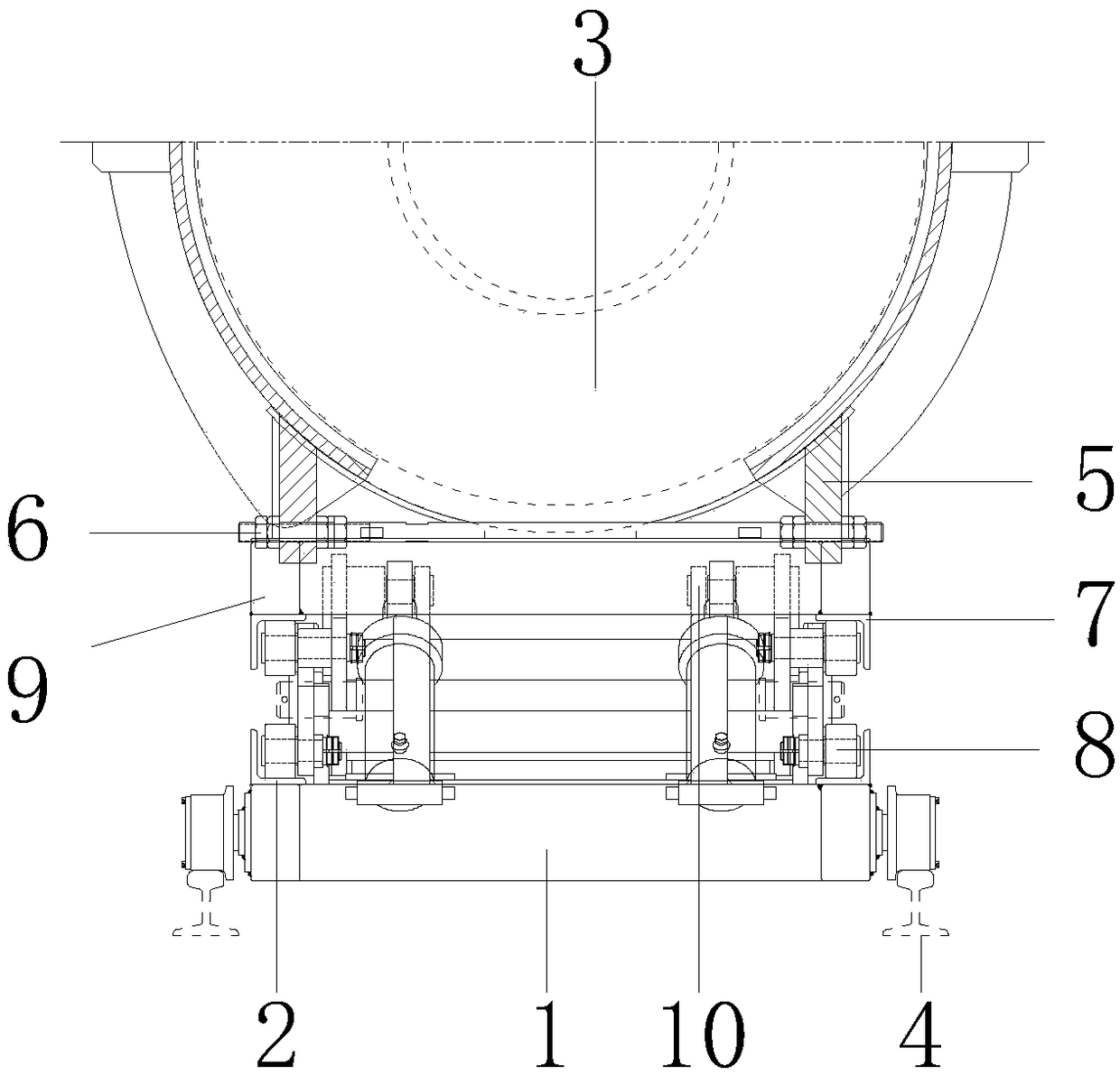
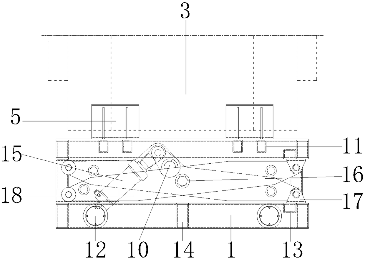
[0016] see Figure 1-4, the present invention provides a technical solution: a foam molding processing device for automobile interior decoration, including a base 1, the base 1 is made of stainless steel, and is used to install various internal parts, and the upper surface of the base 1 is equipped with a connecting corner code 2 , the connecting corner code 2 is made of stainless steel, which is used to connect and fix the triangular plate 17, the inner wall of the connecting corner code 2 is connected with the outer wall of the base 1, and a bottom cover 23 is installed on the right side outer wall of the base 1, and the bottom cover 23 is made of stainless steel, and is used for Gasket 25 is installed, the left side outer wall of bottom cover 23 is connected with the right side outer wall of base 1, and gasket 25...


PUM


Abstract

The invention discloses a machining device for automotive trim foam molding. The machining device comprises a base; a triangular plate is mounted on the upper surface of the base; the lower surface ofthe triangular plate is connected with the upper surface of the base; an ejector rod is mounted on the inner wall of the triangular plate; the outer wall of the ejector rod is connected with the inner wall of the triangular plate; a main shaft is mounted on the inner wall of the ejector rod; the outer wall of the main shaft is connected with the inner wall of the ejector rod; and an inclined support sleeves the outer wall of the main shaft. The machining device for automotive trim foam molding overcomes instable connection between a movable plate and a compression spring in a traditional machining device for automotive trim foam molding, overcomes the defect of loose extrusion of machined parts caused by loose connection of upper and lower molds in the traditional machining device for automotive trim foam molding when the upper mold downwards moves to extrude with the lower mold, saves finished products, improves the machining efficiency, and is suitable for popularization and application.

Description

technical field [0001] The invention relates to the technical field of automobile manufacturing, in particular to a foam molding processing device for automobile interior decoration. Background technique [0002] With the development of China's automobile industry, people's requirements for the appearance, comfort, safety, and energy saving of automobiles are constantly improving, and the amount of plastic products used in auto parts is also increasing. Mold processing equipment is used, but the existing mold processing equipment often causes the problem of difficulty in picking up parts. The formed mold usually needs to be removed manually, which wastes a lot of manpower time, seriously affects production efficiency, and causes waste of resources. In the prior art, for example, the invention patent with the application number 201620383920.0 includes a main body, the top of the main body is provided with a material inlet, the inside of the main body is provided with a storag...

Claims


Application Information

Patent Timeline
IPC IPC(8): B29C44/02B29C44/34B29C44/58B29L31/58
CPCB29C44/02B29C44/35B29C44/58B29L2031/58
Inventor 张晨毅金乐贫章云张娉
Owner WUHU HUANRUI AUTO INTERIOR DECORATION
Why Eureka
Try Eureka