
Multi-axis freely-adjustable unmanned aerial vehicle holder

A machine-head, free technology, applied in the field of multi-axis freely adjustable drone head, can solve the problems of unstable head movement, poor shooting effect and customer experience, etc., to achieve the effect of increasing the shooting range

Inactive Publication Date: 2018-05-22
陈益德
View PDF9 Cites 5 Cited by
  • Summary
  • Abstract
  • Description
  • Claims
  • Application Information

AI Technical Summary

Problems solved by technology

[0002] At present, the gimbal installation methods of traditional unmanned aerial vehicles are mostly fixed and quick-release. After installation, the position of the gimbal cannot be changed. The shooting and video recording device on the gimbal will be blocked by the aircraft support frame or even the aircraft body when it rotates with the gimbal to shoot video. The shooting effect and customer experience are not good. In order to solve this problem in the prior art, the gimbal is designed as a telescopic The gimbal, when the UAV flies into the air, the gimbal can be expanded through the telescopic bracket to expand the shooting range of the camera. The machine base and the pan / tilt are connected by hinges, so the elongation and shortening of the stretch can control the rise and fall of the camera, but because the two ends of the telescopic frame are hinged structures, the movement of the pan / tilt is not very stable, so we propose a Multi-axis free adjustment UAV gimbal to solve the above problems

Method used


Image

  • Multi-axis freely-adjustable unmanned aerial vehicle holder
  • Multi-axis freely-adjustable unmanned aerial vehicle holder
  • Multi-axis freely-adjustable unmanned aerial vehicle holder

Examples


Embodiment Construction

[0017] The following will clearly and completely describe the technical solutions in the embodiments of the present invention with reference to the accompanying drawings in the embodiments of the present invention. Obviously, the described embodiments are only some, not all, embodiments of the present invention. Based on the embodiments of the present invention, all other embodiments obtained by persons of ordinary skill in the art without making creative efforts belong to the protection scope of the present invention.

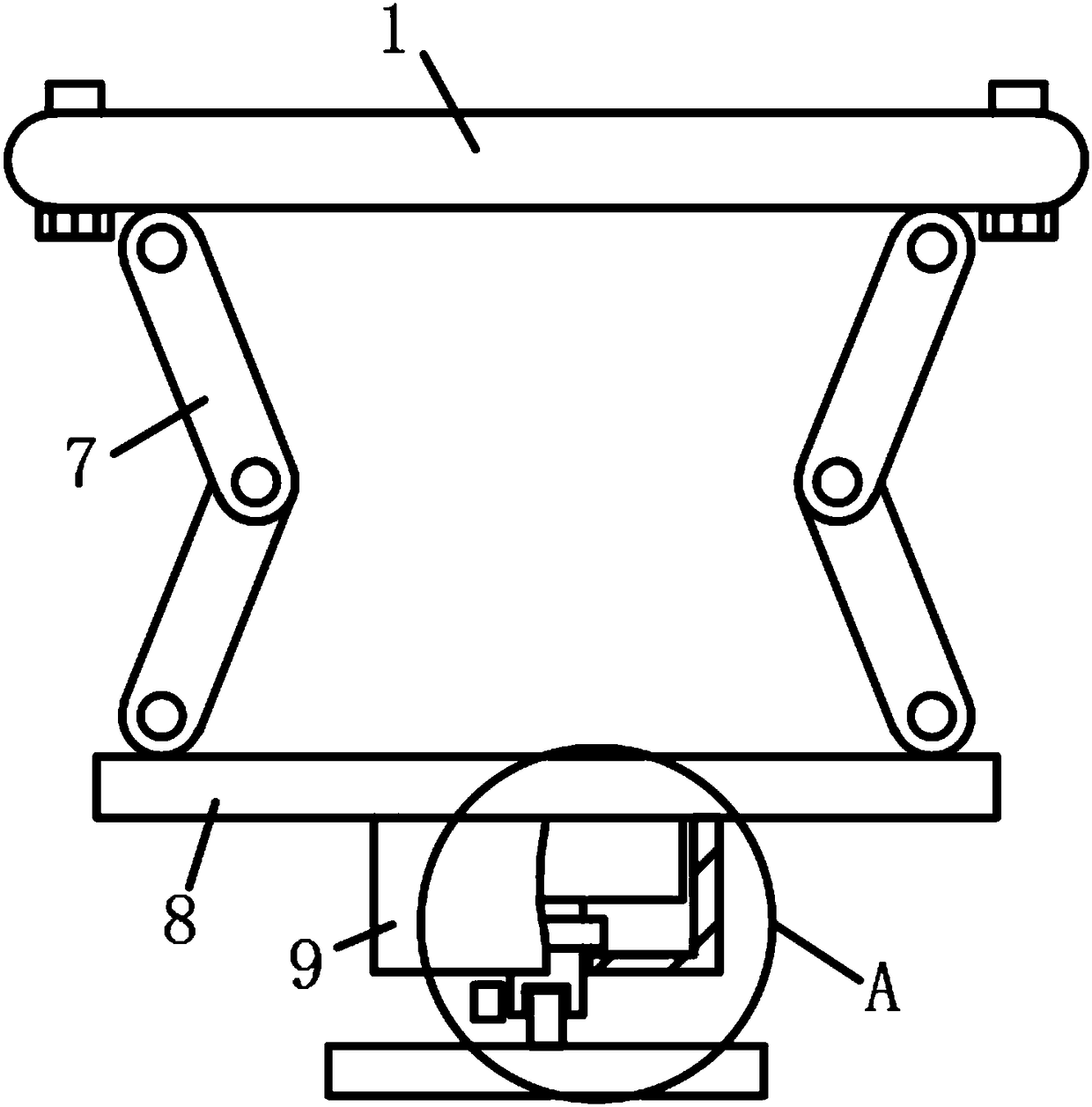
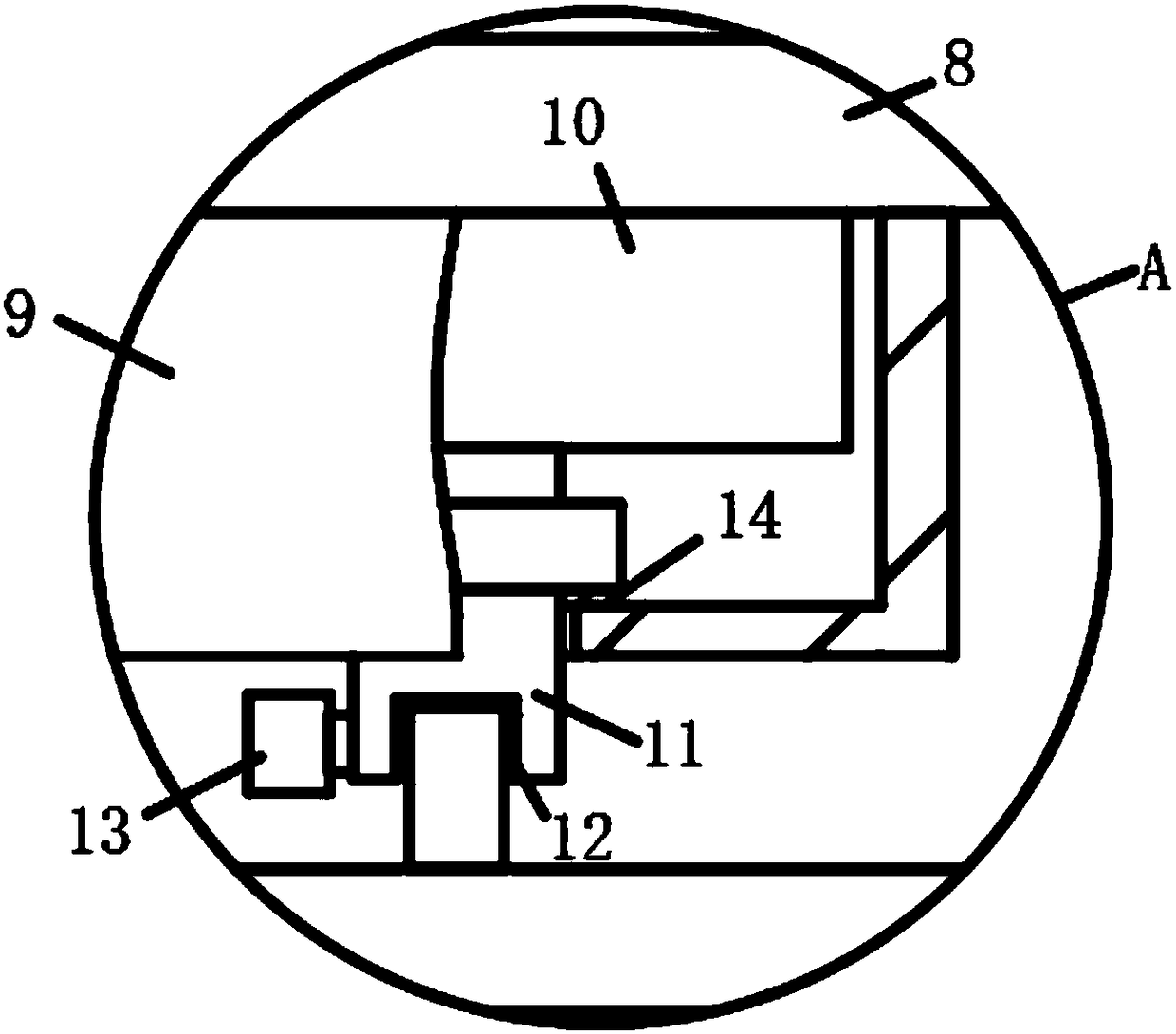
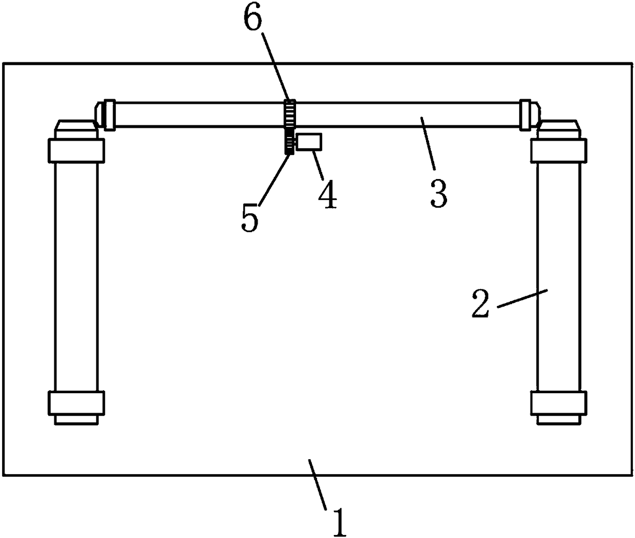
[0018] see Figure 1-3 , the present invention provides a technical solution: a multi-axis freely adjustable unmanned aerial vehicle platform, including a connecting plate 1, the lower surface of the connecting plate 1 is axially equipped with two rotating shafts 2, and one end of the two rotating shafts 2 is Bevel gear structure, the lower surface of the connecting plate 1 is equipped with a transmission shaft 3, the length direction of the transmission shaft...


PUM


Abstract

The invention discloses a multi-axis freely-adjustable unmanned aerial vehicle holder. The holder comprises a connecting plate; two rotating shafts are installed on the lower surface of the connectingplate in a shaft driving mode, and one end of each rotating shaft is of a bevel gear structure; a transmission shaft is installed on the lower surface of the connecting plate in a shaft driving mode,and the two ends of the transmission shaft are in meshing connection with the bevel gear structures of the two rotating shafts respectively; a transmission motor is electrically installed on the lower surface of the connecting plate. According to the holder, the transmission motor can drive a driving gear to rotate after being started to rotate, the driving gear drives a driven gear to rotate when rotating, as the driven gear fixedly sleeves the rotating shafts, the rotating shafts can drive upper folding rod bodies to rotate when rotating, folding and unfolding of folding rods are achieved,and thus ascending and descending of a camera are adjusted; the structure is stable, a first steering motor can drive a mounting rack to rotate in the horizontal direction when rotating, and a secondsteering motor can drive the mounting rack to rotate in the vertical direction when rotating.

Description

technical field [0001] The invention relates to the technical field of unmanned aerial vehicles, in particular to a multi-axis freely adjustable unmanned aerial vehicle platform. Background technique [0002] At present, the gimbal installation methods of traditional unmanned aerial vehicles are mostly fixed and quick-release. After installation, the position of the gimbal cannot be changed. The shooting and video recording device on the gimbal will be blocked by the aircraft support frame or even the aircraft body when it rotates with the gimbal to shoot video. The shooting effect and customer experience are not good. In order to solve this problem in the prior art, the gimbal is designed as a telescopic The gimbal, when the UAV flies into the air, the gimbal can be expanded through the telescopic bracket to expand the shooting range of the camera, but this telescopic bracket is lifted by a pull rope, and the telescopic bracket is a folding bracket, and the upper and lower ...

Claims


Application Information

Patent Timeline
Patent Type & Authority Applications(China)
IPC IPC(8): B64D47/08
CPCB64D47/08
Inventor 陈益德
Owner 陈益德
Learn More