Automatic take-up device for electric power engineering

A wire take-up device and electric power engineering technology, which is applied in the field of electric power engineering, can solve problems such as unadjustable speed, disordered winding order, and reduce wire winding effect, so as to achieve the effect of improving the winding effect

Inactive Publication Date: 2018-05-25
四川新坐标电力设计咨询有限公司
View PDF1 Cites 1 Cited by
  • Summary
  • Abstract
  • Description
  • Claims
  • Application Information

AI Technical Summary

Problems solved by technology

[0002] At present, the take-up reel is a kind of cable storage tool, and the cable is wound on it to facilitate picking and placing. The take-up reel in the prior art usually includes a spool for the cable to be wound and two ends of the spool are relatively arranged to prevent all The baffle that the wound cable falls off from both ends of the spool. When the wire is taken up, the cable is wound on the spool. Although the take-up reel of this structure can make the cable wind up to achieve the purpose of taking up the wire, but because its speed cannot be adjusted During the winding process, there will be jumps that make the winding order chaotic. For example, the invention patent with the application number 201320662097.3 includes a frame. The frame chassis is fixedly connected, the bottom of the chassis is provided with fixed hooks that can be hung horizontally, and the two ends of the chassis are also equipped with locking slant plates. Although this patent improves the efficiency of wire take-up, the actual work is due to the slow speed of wire take-up. Uniform, the wire will appear looped, which reduces the winding effect of the wire

Method used


Image

  • Automatic take-up device for electric power engineering
  • Automatic take-up device for electric power engineering
  • Automatic take-up device for electric power engineering

Examples


Embodiment Construction

[0017] In order to make the object, technical solution and advantages of the present invention clearer, the present invention will be further described in detail below in conjunction with the accompanying drawings and embodiments. It should be understood that the specific embodiments described here are only used to explain the present invention, not to limit the present invention.

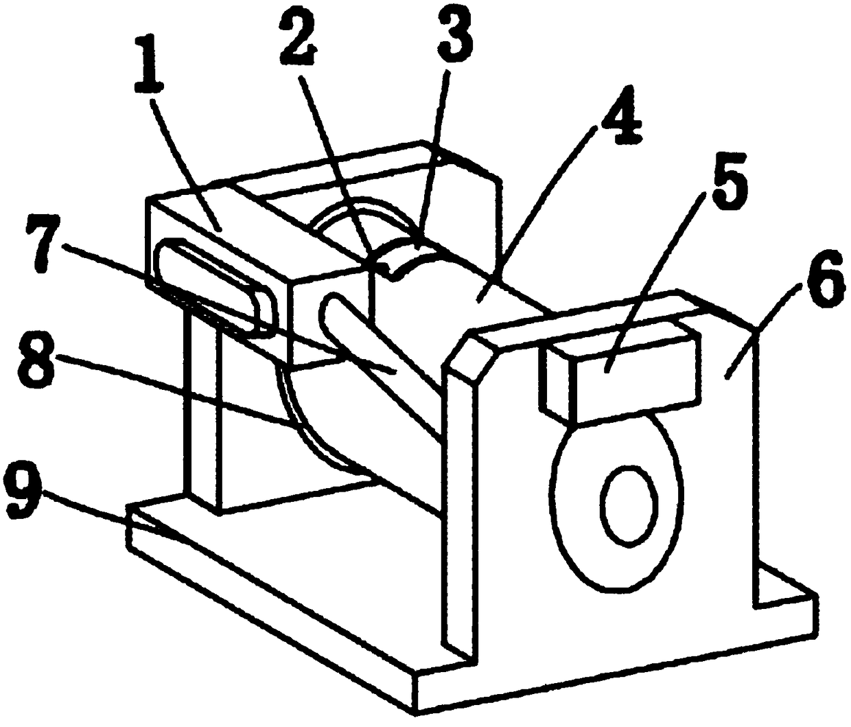
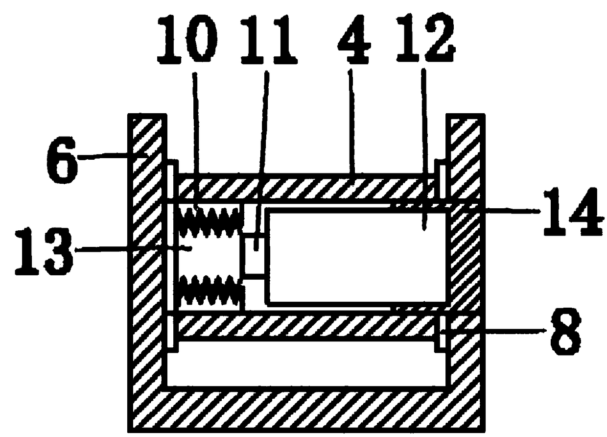
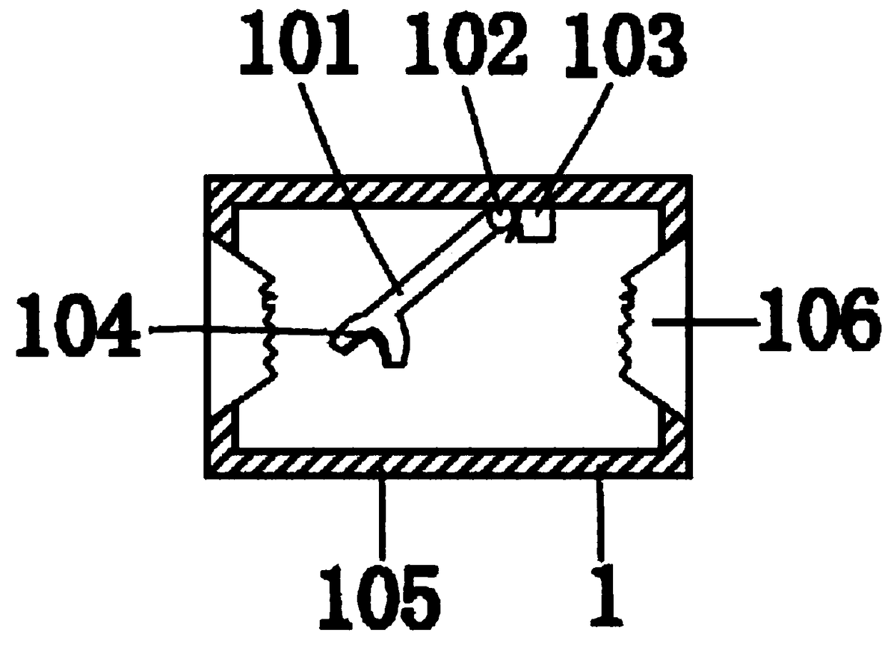
[0018] see Figure 1-Figure 5 The shown automatic wire take-up device for electric power engineering includes a base 9 and side plates 6 arranged at the left and right ends of the base 9, wherein a controller 5 is provided on the top of the outer wall of one end side plate 6, and a controller 5 is arranged between the inner walls of the two end side plates. A rotary roller 4 is provided, and the rotary roller 4 is connected to the side plate 6 through a rotary rail 8. The interior of the rotary roller 4 is provided with an internal tooth 10 and a power device 12, and the inner wall of the internal ...


PUM


Abstract

The invention relates to an automatic take-up device for electric power engineering. The automatic take-up device comprises a base and side plates arranged at the left end and the right end of the base, the top end of the outer wall of the side plate located at one end of the base, a rotary roller is arranged between the inner wall of the side plates located at the two ends of the base and connected with the side plates through rotary rails, inner teeth and a power device are arranged in the rotary roller, a rotary gear is arranged on the inner walls of the inner teeth, the rotary gear is engaged with the inner teeth and connected with the power device through a rotation speed adjuster, and the power device and the rotation speed adjuster are both electrically connected with the controller; a wire discharging device is arranged at the left-end side plate and connected with the side plate through a connection frame and comprises a shell and a pressing ring; and the pressing ring is connected with the inner wall of the top end of the shell through a movable piece, a limiting piece is arranged at the moving piece, and the two side walls of the shell are provided with wire openings ina corresponding mode. The advantage that the electric wire winding effect is improved is achieved.

Description

technical field [0001] The invention relates to the technical field of electric power engineering, in particular to an automatic wire take-up device for electric power engineering. Background technique [0002] At present, the take-up reel is a kind of cable storage tool, and the cable is wound on it to facilitate picking and placing. The take-up reel in the prior art usually includes a spool for the cable to be wound and two ends of the spool are relatively arranged to prevent all The baffle that the wound cable falls off from both ends of the spool. When the wire is taken up, the cable is wound on the spool. Although the take-up reel of this structure can make the cable wind up to achieve the purpose of taking up the wire, but because its speed cannot be adjusted During the winding process, there will be jumps that make the winding order chaotic. For example, the invention patent with the application number 201320662097.3 includes a frame. The frame chassis is fixedly con...

Claims


Application Information

Patent Timeline
IPC IPC(8): B65H54/44B65H75/28B65H63/00B65H57/06B65H57/26
CPCB65H54/44B65H57/06B65H57/26B65H63/00B65H75/28B65H2701/34
Inventor 阳华波
Owner 四川新坐标电力设计咨询有限公司
Why Eureka
Try Eureka