
Discharge device of capacitor nailing machine

A capacitor and nailing technology, which is applied in the field of capacitor nailing machine blanking device, can solve the problems of defective products, unsmooth feeding, and bending of guide pins, etc., and achieve the effect of fast transmission speed and stable transmission speed

Pending Publication Date: 2018-05-25
SHENZHEN CHENGJIE INTELLIGENT EQUIP CO LTD
View PDF0 Cites 6 Cited by
  • Summary
  • Abstract
  • Description
  • Claims
  • Application Information

AI Technical Summary

Problems solved by technology

[0002] At present, the structure of conventional nailing machines on the market generally uses a minute needle mechanism to separate the guide pins arranged together. The minute needle stick is easy to bend the guide pin, and at the same time, it is easy to cause the guide pin to be messed up, scratched, and the material feeding is not smooth, which will cause defective products and waste materials

Method used


Image

  • Discharge device of capacitor nailing machine
  • Discharge device of capacitor nailing machine
  • Discharge device of capacitor nailing machine

Examples


Embodiment Construction

[0041] In order to make the purpose, technical solution and technical effect of the present invention clearer, the present invention will be further described in detail below in conjunction with the accompanying drawings and specific implementation methods. It should be understood that the specific implementations described in this specification are only for explaining the present invention, not for limiting the present invention.

[0042] It should be noted that when an element is referred to as being “fixed” or “disposed on” another element, it may be directly on the other element or be indirectly on the other element. When an element is referred to as being "connected to" another element, it can be directly connected to the other element or indirectly connected to the other element.

[0043] It is to be understood that the terms "length", "width", "top", "bottom", "front", "rear", "left", "right", "vertical", "horizontal", "top" , "bottom", "inner", "outer" and other indic...


PUM


Abstract

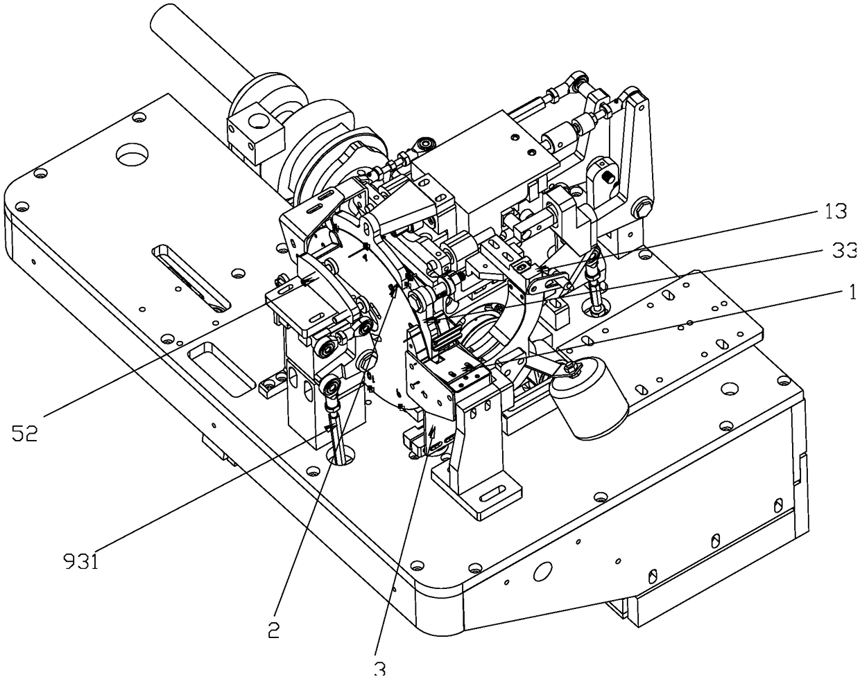
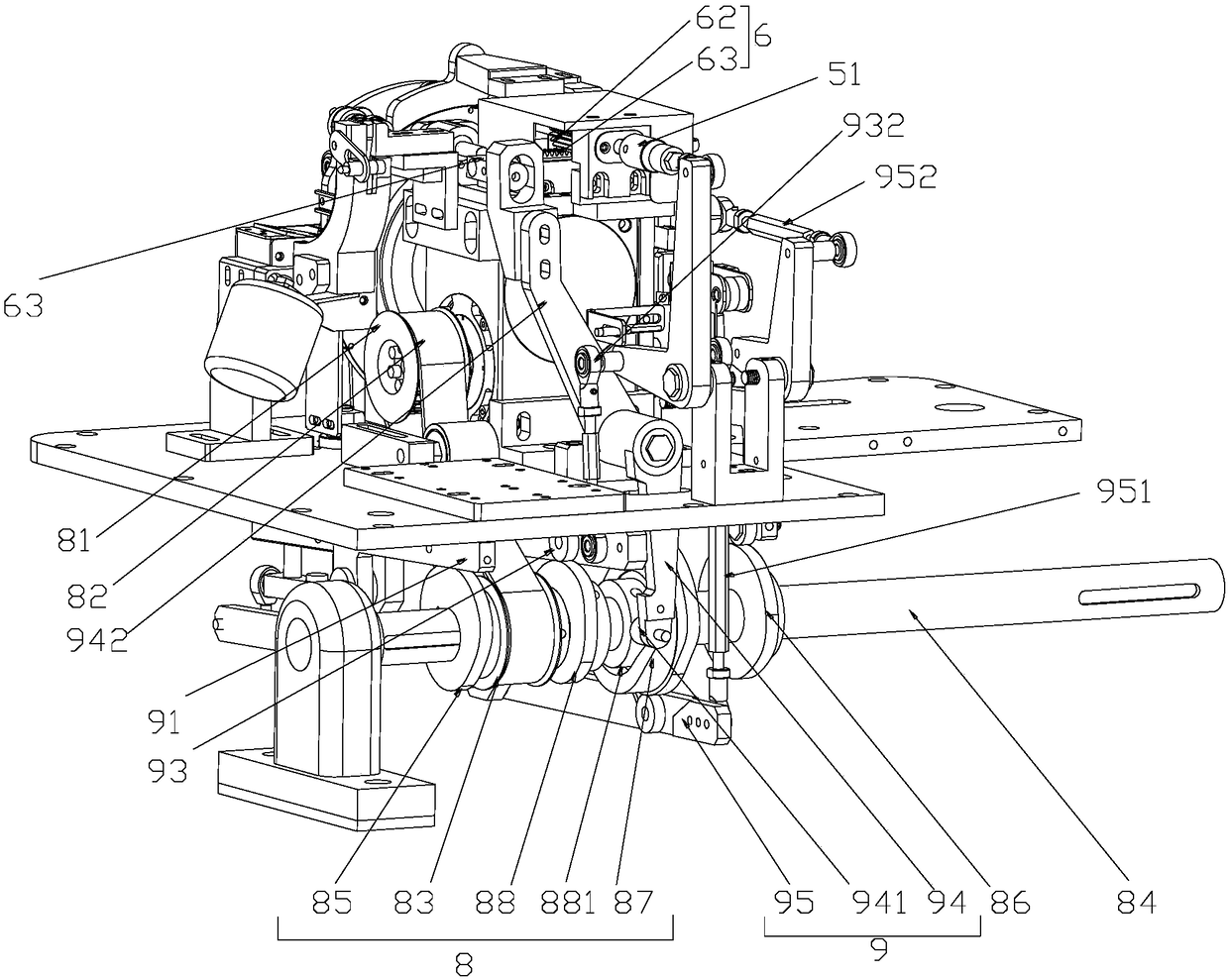
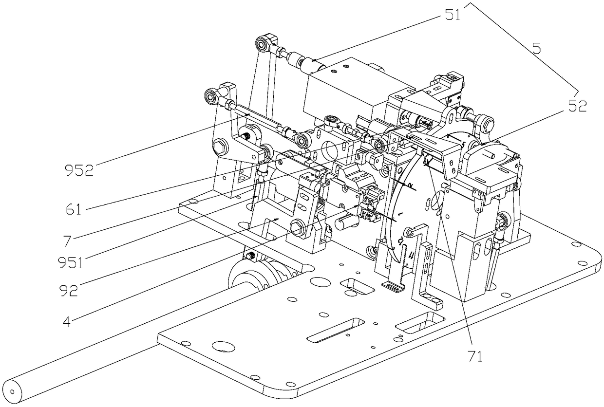
The invention discloses a discharge device of a capacitor nailing machine. The discharge device comprises a discharge hopper, a rotating plate, a feeding mechanism, a needle taking clamp and a drivingmechanism, wherein the discharge hopper is provided with a guide needle inlet and a guide needle outlet, the guide needle outlet is located at the bottom of the discharge hopper, the rotating plate is provided with a station groove for magnetically attracting a guide needle and rotationally conveys the guide needle. The station groove is located in the circumference of the rotating plate. The feeding mechanism comprises a needle ejecting plate. The top face of the needle ejecting plate is located at the guide needle outlet of the discharge hopper. The needle ejecting plate moves up to send the guide needle to a groove opening of the station groove of the rotating plate to be magnetically attracted into the station groove. The needle taking clamp is located at the position, at the tail endof the rotating trajectory of the rotating plate, of the guide needle and used for taking down the guide needle in the station groove of the rotating plate. The driving mechanism is connected with the needle ejecting plate and the needle taking clamp and used for driving the needle ejecting plate and the needle taking clamp to move. The discharge device is rapid and stable in guide needle conveying, and twelve stations are used for conveying during the intermittent movement of the plate so that the guide needle can be corrected and completely positioned.

Description

technical field [0001] The invention belongs to the technical field of capacitor preparation, and more specifically, the invention relates to a capacitor nailing machine unloading device. Background technique [0002] At present, the structure of conventional nailing machines on the market generally uses a minute needle mechanism to separate the guide pins arranged together. When the minute needle bar of the minute needle mechanism is not inserted between two adjacent guide pins and the end of the minute needle bar collides with the guide pins The minute needle stick is easy to bend the guide pin, and at the same time, it is easy to cause the guide pin to be messed up, scratched, and the material feeding is not smooth, which will cause defective products and waste materials. Contents of the invention [0003] The purpose of the present invention is to: aim at the above-mentioned defects of the prior art, to provide a guide pin transmission and positioning device for a capa...

Claims


Application Information

Patent Timeline
Patent Type & Authority Applications(China)
IPC IPC(8): H01G13/00
CPCH01G13/00H01G13/006
Inventor 何凤明张云艳李友舟陈永昌
Owner SHENZHEN CHENGJIE INTELLIGENT EQUIP CO LTD
Learn More