Rotating self-pulling type framework gasket

A self-pulling, skeleton technology, used in gaskets, connecting components, mechanical equipment, etc., can solve the problems of increasing the difficulty of card processing, destroying the consistency of the card, and inconvenient use of skeleton gaskets, so as to improve product assembly quality and The effect of assembly efficiency, shortening production cycle and improving production efficiency

Active Publication Date: 2019-02-22
JIANGXI HONGDU AVIATION IND GRP
View PDF11 Cites 0 Cited by
  • Summary
  • Abstract
  • Description
  • Claims
  • Application Information

AI Technical Summary

Problems solved by technology

[0004] 1. The steps are cumbersome, and the wing nut needs to be loosened and tightened repeatedly, which wastes labor costs, reduces the service life of the skeleton gasket, and reduces the assembly accuracy;
[0005] 2. Opening the exit groove of the skeleton gasket on the pallet will destroy the consistency of the pallet, reduce the product profile that the pallet can be positioned on, and make the profile of the pallet incomplete. If there is a protruding rivet head Due to the limited exit space, in order to prevent the gasket from interfering with the rivet head, the exit groove on the pallet needs to be deepened before it can be used, which increases the damage to the pallet and increases the Difficult to process and easy to cause card board damage
[0006] 3. If a round-head rivet is used at the joint of the aircraft skin, that is, when the rivet head protrudes from the skin shape, it will be inconvenient or impossible to use the skeleton gasket in this form.

Method used


Image

  • Rotating self-pulling type framework gasket
  • Rotating self-pulling type framework gasket
  • Rotating self-pulling type framework gasket

Examples


Embodiment 1

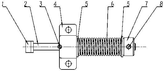
[0025] Example 1, see image 3 —— Figure 5 A rotating self-pull-type skeleton gasket shown includes a skeleton profile 1, a rod 2 and a positioning block 4. One end of the rod 2 is provided with a skeleton profile 1, and the other end is provided with a nut 7. The body of the rod 2 The pre-compression limiter is equipped with a positioning block 4, and the positioning block 4 includes an upper plate 41, a vertical plate 42 and a lower plate 43, and one side of the upper part of the lower plate 43 is provided with an upper plate 41 through the vertical plate 42, and the vertical plate 42 is provided with an upper plate 41. There are rod through holes, and the front and rear sides of the lower part of the lower plate 43 are respectively extended outwards to be provided with mounting ears 44, and the mounting ears 44 are provided with mounting holes 45, and the rod 2 is radially provided with pin holes, and the pin holes are provided with The cylindrical pin 3, the upper plate ...


PUM


Abstract

The invention discloses a rotating self-puling type framework gasket which comprises a framework appearance piece, a rod and a positioning block. The framework appearance piece is arranged at one endof the rod, and the other end of the rod is sleeved with a nut. The positioning block is installed at the body portion of the rod in a pre-compressing and limiting manner. The positioning block comprises an upper plate, a vertical plate and a lower plate. One side of the upper portion of the lower plate is provided with the upper plate through the vertical plate, and a rod passing hole is formed in the vertical plate. Installation lugs are arranged on the front side and the rear side of the lower portion of the lower plate in an outwards-extending manner. Installation holes are formed in the installation lugs, and a pin hole is formed in the rod in the radial direction. A cylindrical pin is arranged in the pin hole. Longitudinal grooves matched with the cylindrical pin in a limiting mannerare formed in the sides, close to the framework appearance piece, of the upper plate and the lower plate. By means of the rotating self-pulling type framework gasket, the appearance of a clamping plate does not need to be damaged, the rotating self-puling type framework gasket is conveniently used at the appearance position of a product with a protruding rivet head, the product assembling qualityand the product assembling efficiency are improved, the manufacturing period of the product is shortened, and therefore the production operation efficiency is effectively improved.

Description

technical field [0001] The invention relates to a rotary self-pull type skeleton gasket. Background technique [0002] In the aircraft assembly process, the positioning pad is also called the skeleton gasket. The skeleton gasket is used to simulate the thickness of the aircraft skin, so that the pallet can not only assemble the product skeleton but also complete the product skin 100 riveting assembly after the assembly is completed. The existing frame spacer refers to [Aviation Industry Standard] HB 611-1989 positioning plate, its front view is as follows figure 2 As shown, when using figure 1 As shown; before assembling the skin 100, it is necessary to simulate the thickness of the skin 100 at the backing plate, install the skeleton gasket on the clamping plate 200, and then tighten the wing nuts to adjust to the correct position; when the skin 100 is installed , it is necessary to loosen the wing nut. In order to prevent the skeleton gasket from interfering with the pro...

Claims


Application Information

Patent Timeline
Patent Type & Authority Applications(China)
IPC IPC(8): F16B43/00
CPCF16B43/00
Inventor 赵梦雪吕冰邹旸郑雪海吴凡赵岩
Owner JIANGXI HONGDU AVIATION IND GRP
Why Eureka
Try Eureka