
driver circuit

A driver circuit, differential driver technology, applied in the direction of logic circuit, logic circuit connection/interface layout, electronic switch, etc., can solve the problems of speeding up the slew rate of the transmitter driver, slowing down the slew rate of the transmitter driver, etc.

Active Publication Date: 2021-05-18
MEDIATEK INC
View PDF4 Cites 0 Cited by
  • Summary
  • Abstract
  • Description
  • Claims
  • Application Information

AI Technical Summary

Problems solved by technology

However, these two conventional designs can only slow down the slew rate of the transmit driver, and these two conventional designs cannot speed up the slew rate of the transmit driver

Method used


Image

  • driver circuit
  • driver circuit
  • driver circuit

Examples


Embodiment Construction

[0025] The following description is a preferred embodiment of the present invention, which is only used to illustrate the technical features of the present invention, but not to limit the scope of the present invention. While certain terms are used throughout the specification and claims to refer to specific elements, those skilled in the art should understand that manufacturers may use different names for the same element. Therefore, the specification and claims do not use the difference in name as the way to distinguish components, but use the difference in function of the components as the basis for the difference. The terms "element", "system" and "apparatus" used in the present invention may be a computer-related entity, where the computer may be hardware, software, or a combination of hardware and software. The terms "comprising" and "including" mentioned in the following description and claims are open terms, so they should be interpreted as "including, but not limited ...


PUM


Abstract

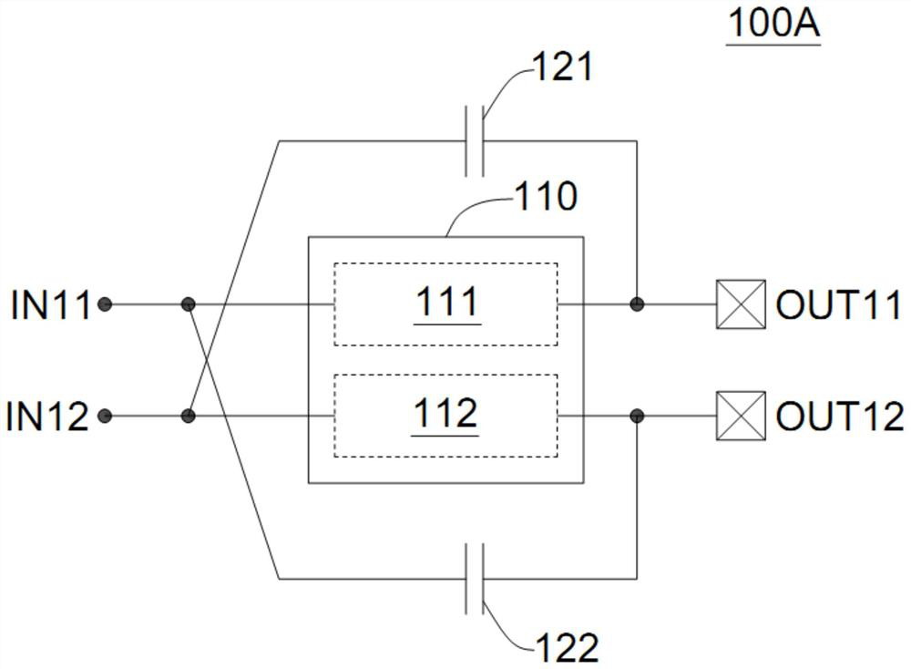
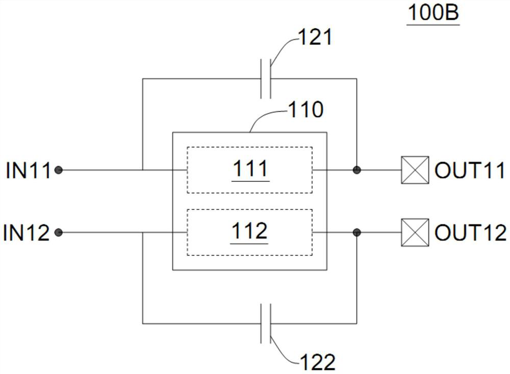
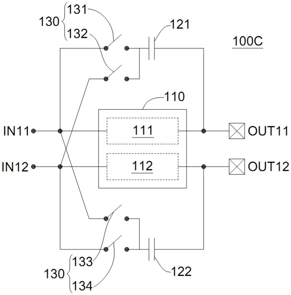
The invention provides a driver circuit. The driver circuit includes: a differential driver, a first feedback passive circuit and a second feedback passive circuit. The differential driver has a first input point, a second input point, a first output point and a second output point. The first feedback passive circuit is coupled to the second input point and the first output point. The second feedback passive circuit is coupled to the first input point and the second output point. The invention can slow down or speed up the slew rate of the driver circuit.

Description

technical field [0001] The present invention relates to an electronic circuit, and more particularly, to a driver circuit. Background technique [0002] In the traditional serializer (SERDES) design, in order to slow down the slew rate of the transmitter driver, using a delay line to switch part of the drivers one by one and adding a capacitor at the output point are two traditional designs. However, these two conventional designs can only slow down the slew rate of the transmit driver, and these two conventional designs cannot speed up the slew rate of the transmit driver. [0003] In some cases, it is desirable to speed up the slew rate of the transmit driver. So researchers have tried to improve these designs to selectively slow and speed up the slew rate of the launch driver. Contents of the invention [0004] In view of this, one object of the present invention is to provide a driver circuit to solve the above problems. [0005] In an exemplary embodiment, a driver...

Claims


Application Information

Patent Timeline
Patent Type & Authority Patents(China)
IPC IPC(8): H03K19/01
CPCH03K19/01H03K19/0185H03K17/04
Inventor 吴建桦
Owner MEDIATEK INC
Learn More