
Patsnap Eureka
For R&D, Patsnap Eureka makes reading and utilizing patents & technical documents easy.
Patsnap Eureka AIR
Designed for self-driven R&D workflows. Generate viable solutions, solve complex R&D challenges, empower your innovation with AI.

Patsnap Eureka Materials
Designed for material experts only. Revolutionize your material R&D, from search, analyze, to developing new materials.

TechResearch
Generate reliable direction feasibility study reports for your R&D in just a few steps.

TechSeek
Discover and master advanced knowledge NOW. Basics, ideas, possibilities, all at once.

TechMind
As an expert in R&D Theories, TechMind can generates customized viable solutions instantly.

TechRisk
Analyze your overall solution with one click, know your potential R&D risks in advance.

TechMonitor
Get weekly tech updates, stay abreast of the latest tech innovations and key insights.
Driver circuit
A technology of driver circuit and differential driver, which is applied in the direction of logic circuit, logic circuit connection/interface layout, electrical components, etc., and can solve the problems of accelerating the conversion rate of the emission driver and slowing down the conversion rate of the emission driver.
- Summary
- Abstract
- Description
- Claims
- Application Information
AI Technical Summary
Problems solved by technology
Method used
Image

Examples
Embodiment Construction
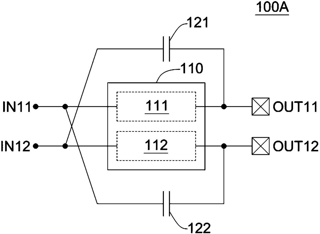
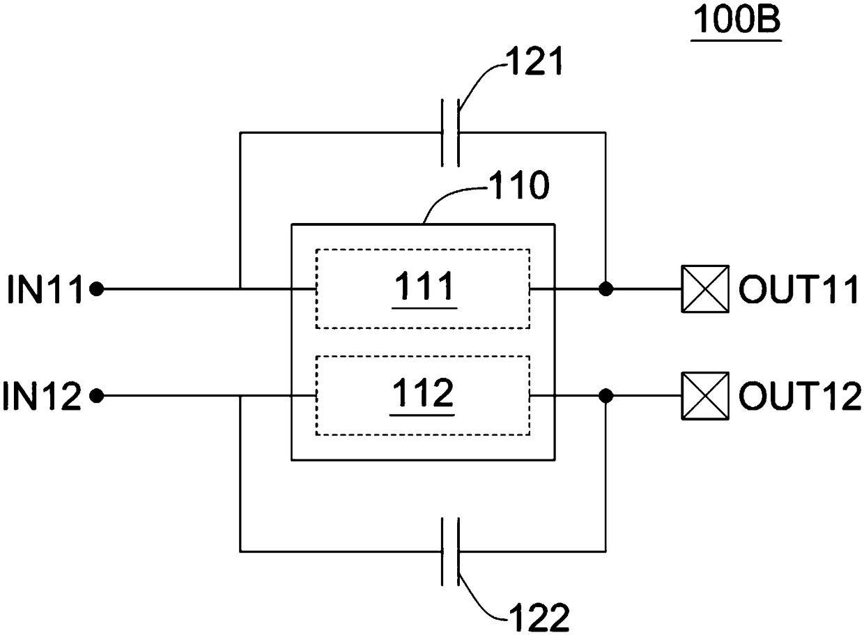
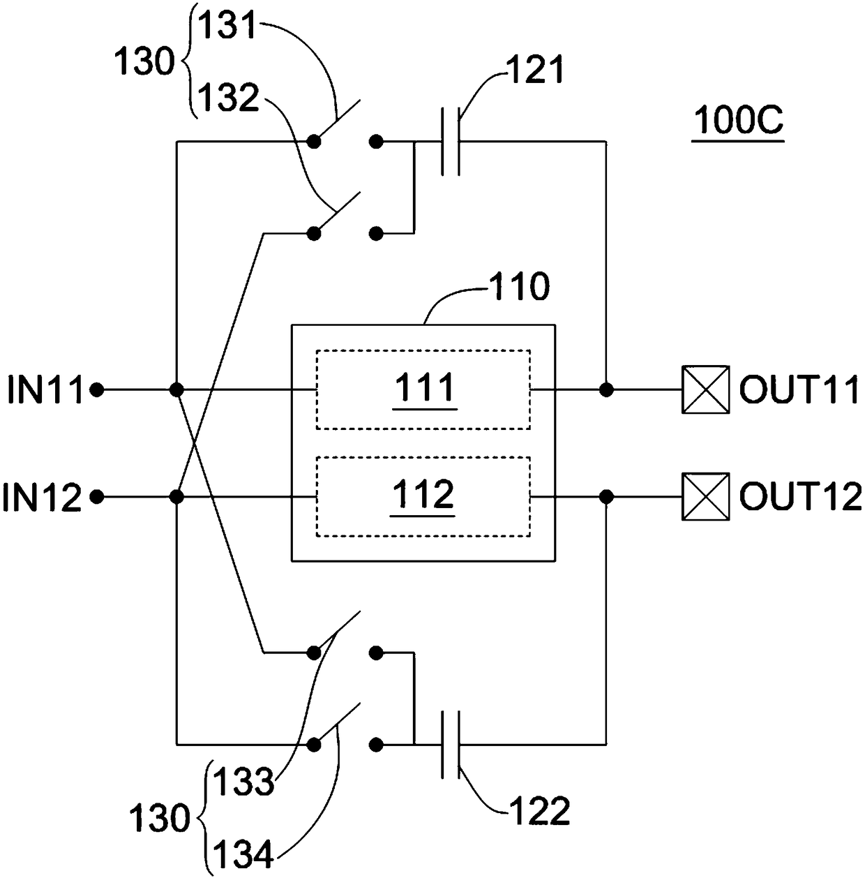
[0025] The following description is a preferred embodiment of the present invention, which is only used to illustrate the technical features of the present invention, but not to limit the scope of the present invention. While certain terms are used throughout the specification and claims to refer to specific elements, those skilled in the art should understand that manufacturers may use different names for the same element. Therefore, the specification and claims do not use the difference in name as the way to distinguish components, but use the difference in function of the components as the basis for the difference. The terms "element", "system" and "apparatus" used in the present invention may be a computer-related entity, where the computer may be hardware, software, or a combination of hardware and software. The terms "comprising" and "including" mentioned in the following description and claims are open terms, so they should be interpreted as "including, but not limited ...
PUM
 Abstract
Description
Claims
Application Information
 - R&D Engineer
- R&D Manager
- IP Professional
- Industry Leading Data Capabilities
- Powerful AI technology
- Patent DNA Extraction
Browse by: Latest US Patents, China's latest patents, Technical Efficacy Thesaurus, Application Domain, Technology Topic, Popular Technical Reports.
© 2024 PatSnap. All rights reserved.Legal|Privacy policy|Modern Slavery Act Transparency Statement|Sitemap|About US| Contact US: help@patsnap.com