
Camera lens, camera module and terminal

A camera lens and camera module technology, which is applied in the field of optical imaging, can solve the problems of increased image sensor format, difficulty in further increasing the total thickness and area of ​​camera lenses, and increased TTL parameters, so as to reduce chromatic aberration, meet miniaturization, The effect of small TTL

Active Publication Date: 2018-12-18
HUAWEI TECH CO LTD
View PDF8 Cites 16 Cited by
  • Summary
  • Abstract
  • Description
  • Claims
  • Application Information

AI Technical Summary

Problems solved by technology

With the evolution of smartphone hardware performance, image sensors with larger sizes and higher resolutions (such as 1 / 2.8 inches to 1 / 2.3 inches) have begun to be widely used. As image sensors become larger and larger, the current The mainstream camera lens design scheme will inevitably lead to further increase of TTL parameters
However, due to the limitation of the size of the smartphone, it is difficult to further increase the total thickness and area of ​​the camera lens, and it will be more difficult to meet the requirements of miniaturization and high imaging quality at the same time.
[0007] To sum up, for the design of the camera lens, it is currently a severe technical challenge to meet the requirements of miniaturization and high imaging quality, but also to meet the needs of the image sensor format increase

Method used


Image

  • Camera lens, camera module and terminal
  • Camera lens, camera module and terminal
  • Camera lens, camera module and terminal

Examples


Embodiment Construction

[0056] Embodiments of the present invention will be described below with reference to the drawings in the embodiments of the present invention.

[0057]The terms used in the embodiments of the present invention are only used to explain specific examples of the present invention, and are not intended to limit the present invention. First, the concept of aberration involved in the embodiment of the present invention is explained. Aberration (aberration) refers to the inconsistency between the results obtained by non-paraxial ray tracing and the results obtained by paraxial ray tracing in the optical system, and the deviation from the ideal state of Gaussian optics (first-order approximation theory or paraxial ray) . Aberration is divided into two categories: chromatic aberration (chromatic aberration, or chromatic aberration) and monochromatic aberration (monochromatic aberration). Chromatic aberration is due to the refractive index of the lens material is a function of wavele...


PUM


Abstract

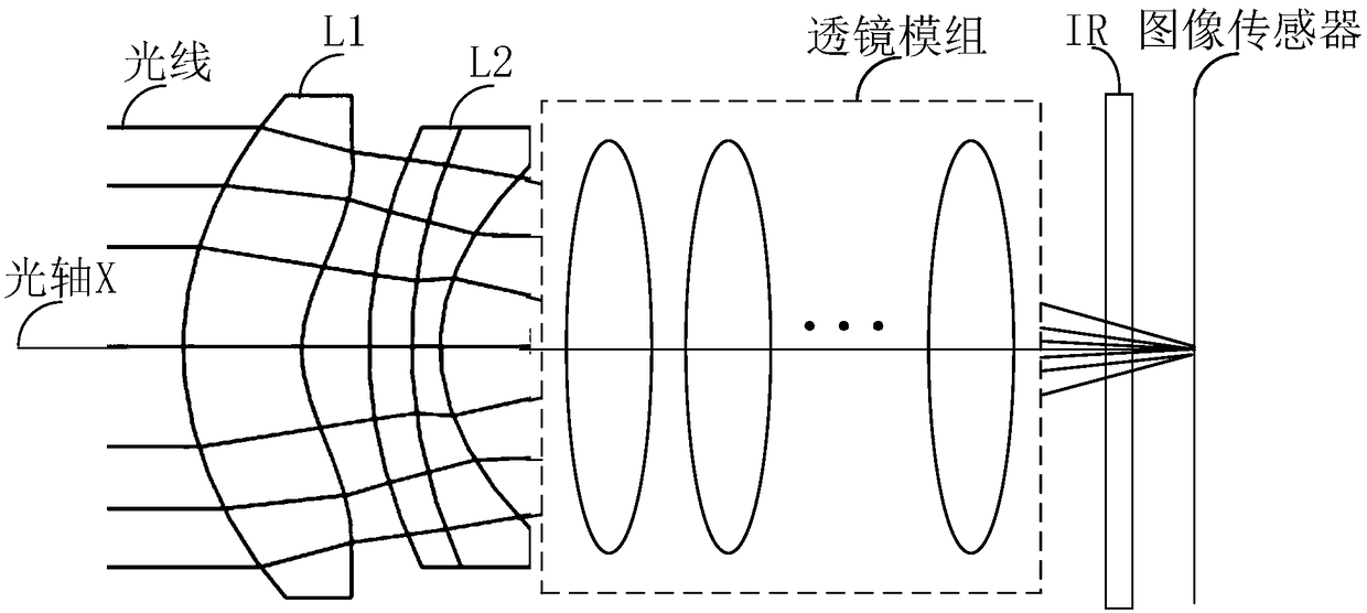
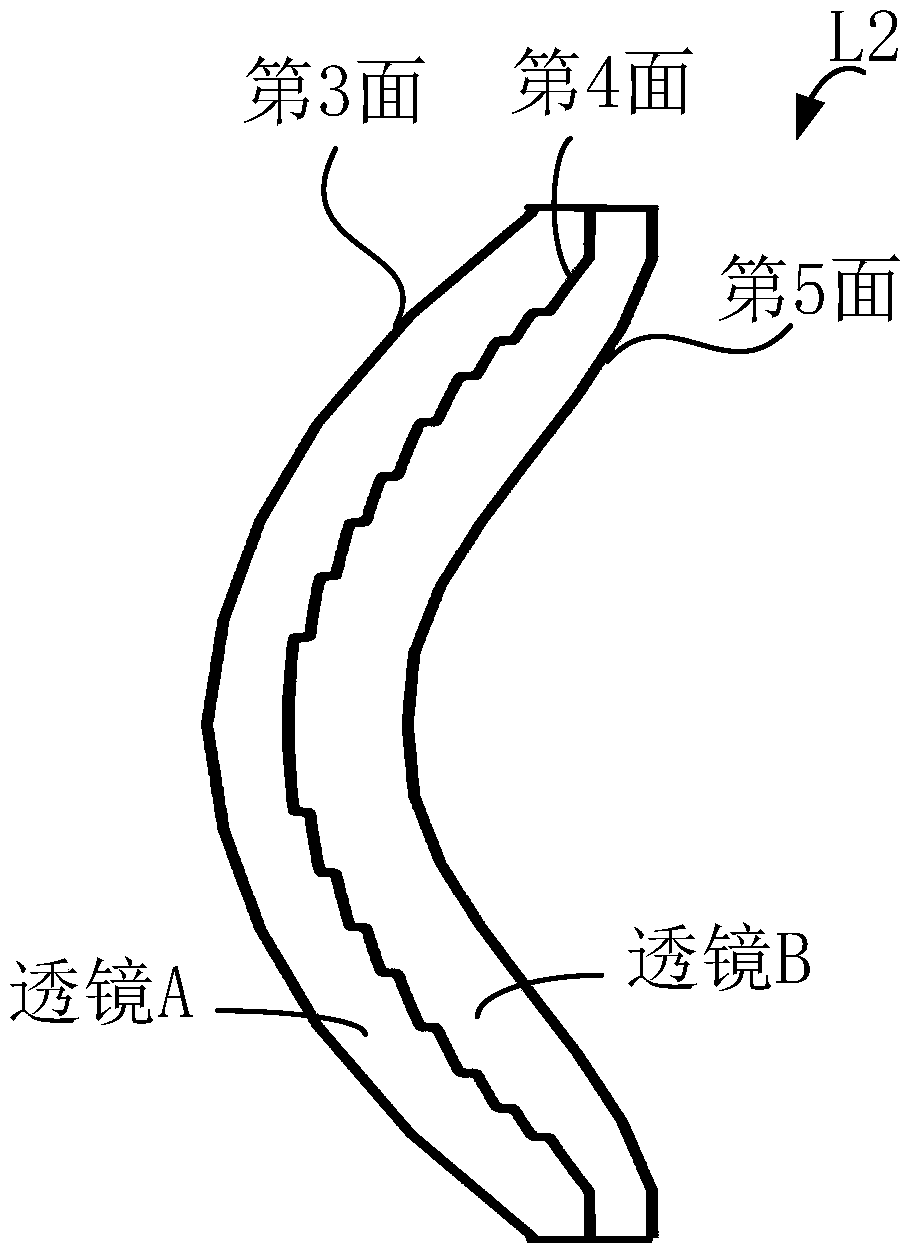
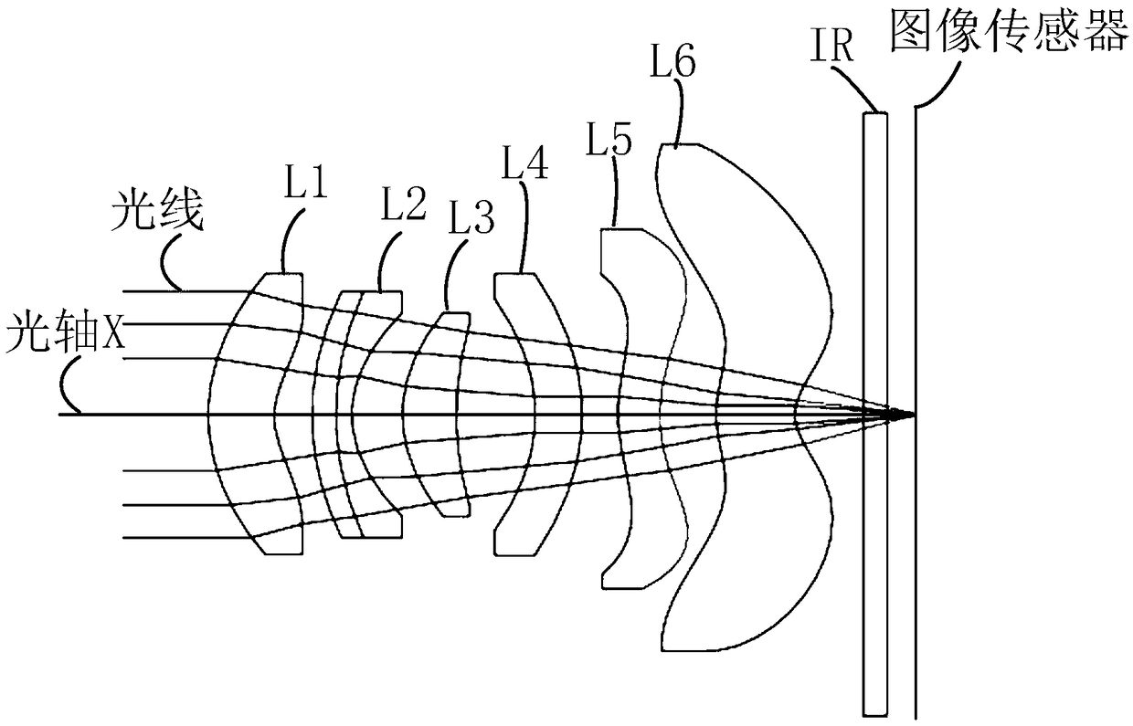
The application provides a camera lens, a camera module, and a terminal. The camera lens includes a first lens, a diffractive optical element, and a lens module along an optical axis from the object surface to the image surface; the surface of the first lens facing the object surface is a convex surface at the optical axis, and the surface facing the image surface is a concave surface, having a positive focal power; the diffractive optical element has a positive focal power and includes a surface facing the object surface, a surface facing the image surface, and a diffractive surface between the two surfaces, the surface facing the object surface is a convex surface at the optical axis, and the surface facing the image surface is a concave surface at the optical axis; the lens module includes N lenses, at least one of the surface facing the object surface and the surface facing the image surface of each of the N lenses is an aspheric surface, and the lens module has a positive focal power. The camera lens provided by the application can meet the requirements of miniaturization and high image quality, and meet the demand for size increase of the image sensor.

Description

technical field [0001] The invention relates to the technical field of optical imaging, in particular to a camera lens, a camera module and a terminal. Background technique [0002] In recent years, with the development of smart terminal technology, the shooting function has become an essential feature of many smart terminals (such as smart phones). Taking a smart phone as an example, the camera lens is the core component of the camera module of the smart phone, and its technology has been developed rapidly. With the development of time and technology, user demands for the miniaturization of smartphones and high image quality (large aperture) for shooting functions are increasing. [0003] Generally speaking, the evaluation parameters of high imaging quality include optical indicators of aberrations such as chromatic aberration, monochromatic aberration (including astigmatism, distortion, spherical aberration, etc.), in order to obtain high imaging quality, a sufficiently l...

Claims


Application Information

Patent Timeline
Patent Type & Authority Applications(China)
IPC IPC(8): G02B13/00G02B13/18G02B1/04H04N5/225
CPCG02B13/0045G02B13/0075G02B13/18G02B1/04H04N23/55G02B13/0055G02B27/4211G02B27/4205
Inventor 於丰安澤卓也野田百合
Owner HUAWEI TECH CO LTD
Learn More