Heart pacing device, and fixing method and conveying system thereof

A technology for cardiac pacing and pacemaker, which is applied in the field of medical devices and can solve the problems that lead-free pacemakers cannot achieve double-chamber pacing, easily penetrate the atrium, and lead-free pacemakers are not firmly fixed.

Active Publication Date: 2018-05-29
MICROPORT SORIN CRMSHANGHAICO LTD
View PDF11 Cites 10 Cited by
  • Summary
  • Abstract
  • Description
  • Claims
  • Application Information

AI Technical Summary

Problems solved by technology

[0005] An object of the present invention is to provide a cardiac pacemaker and its fixing method and delivery system, so as to solve the problems in the prior art that the leadless pacemaker is not firmly fixed and easily penetrates the atrium
[0006] Another object of the present invention is to provide a cardiac pacing device and its fixing method and delivery system, so as to solve the problem that the leadless pacemaker in the prior art cannot realize dual-chamber pacing

Method used


Image

  • Heart pacing device, and fixing method and conveying system thereof
  • Heart pacing device, and fixing method and conveying system thereof
  • Heart pacing device, and fixing method and conveying system thereof

Examples


Embodiment 1

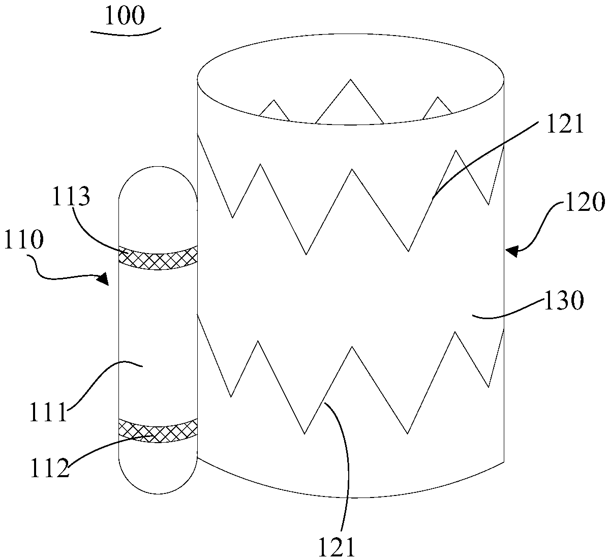
[0053] figure 1 It is a structural schematic diagram of a cardiac pacing device according to Embodiment 1 of the present invention. The cardiac pacing device is used for cardiac pacing to improve arrhythmia.

[0054] refer to figure 1 , the cardiac pacemaker 100 includes a leadless pacemaker 110 and a ring stent 120 , and the leadless pacemaker 110 is at least partially disposed on the ring stent 120 . Here, the leadless pacemaker 110 is installed on the ring-shaped support 120, so as to be fixed in the human body tissue through the ring-shaped support 120, for example, in order to realize dual-chamber pacing, the leadless pacemaker 110 is fixed on the The inferior vena cava connects 311 to the junction of the right atrium 312, thereby enabling dual-chamber pacing.

[0055] Wherein, the ring-shaped stent 120 has a self-expanding property, specifically, the ring-shaped stent 120 has a first size (outer diameter) under a first environment restricting its rebound, and expands t...

Embodiment 2

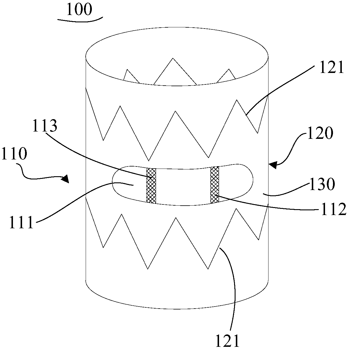
[0077]The applicant found that the implantation positions of the pacing electrodes 112 and the sensing electrodes 113 in the heart have a great influence on the pacing electrical parameters. To obtain better pacing electrical parameters, the position of the electrodes can be adjusted. In order to achieve this purpose, therefore, in order to make the leadless pacemaker 110 have the function of adjusting the electrode position, the housing 111 of this embodiment is movably arranged on the ring-shaped support 120, which is different from the fixed installation of the housing 111 in the first embodiment. It is different on the ring bracket 120 .

[0078] Figure 4 is a schematic structural diagram of a cardiac pacemaker in Embodiment 2 of the present invention, Figure 5 yes Figure 4 The cardiac pacemaker shown is a continuous cross-sectional view along A-A. Such as Figure 4~5 As shown, in addition to the annular structure 121 described in Embodiment 1, the annular bracket 1...

Embodiment 3

[0089] In order to deliver the cardiac pacing device 100 into the body, this embodiment provides a delivery system 200, the structure of the delivery system 200 please refer to Figure 6 , Figure 6 It is a schematic diagram of the composition and structure of the delivery system of the third embodiment of the present invention.

[0090] The delivery system 200 includes an introducer 210 and a conveyor 220 cooperating with the introducer 210 . The conveyer 220 is used for inserting into the introducer 210 to push the cardiac pacemaker 100 inside to the target position, and after reaching the target position, the cardiac pacemaker 100 is released through the conveyer 220 .

[0091] Specifically, such as Figure 7 As shown, the introducer 210 first passes through the femoral vein via the inferior vena cava 311 , the right ventricle 314 to the junction of the superior vena cava 313 and the right atrium 312 . After that, if Figure 8 As shown, the cardiac pacing device 100 is ...


PUM


Abstract

The invention provides a heart pacing device, and a fixing method and a conveying system thereof; the heart pacing device comprises an annular support and a wireless pacing unit at least partially arranged on the annular support; the annular support has a first size with the rebound limited by the first environment, and expands to a second size under the second environment. The heart pacing devicecan be fixed in human body tissues of different wall thicknesses and sizes, and can be easily fixed in a boundary place between the postcava and the right atrium, realizing dual-cavity pacing of thewireless pacing unit, and ensuring the atrium-chamber synchronization physiological pacing. The heart pacing device uses the self-expansion features of the annular support to tightly attach the annular support with protogenesis blood vessel walls, thus fixing the heart pacing device in the heart chamber with a good fixing effect, and preventing heart chamber perforating risks.

Description

technical field [0001] The invention relates to the technical field of medical instruments, in particular to a leadless heart pacemaker. Background technique [0002] Since its introduction in 1958, the pacemaker has become the first-line treatment for bradyarrhythmias. After more than half a century of development and innovation, cardiac pacemakers have been implanted with a single wire through the chest to pace the ventricle, and gradually developed into 2 to 3 wires implanted through the vein to provide atrioventricular physiological pacing, and even bidirectional Synchronous pacing of the ventricles. However, lead-related complications such as lead dislocation, thrombosis, tricuspid regurgitation, and infection have always affected the normal use of pacemakers and endangered the life, health and quality of life of patients. Among them, lead removal has certain Due to the difficulty and risk, this work usually needs to be done in a large electrophysiology center by skil...

Claims


Application Information

Patent Timeline
Patent Type & Authority Applications(China)
IPC IPC(8): A61N1/375
CPCA61N1/362A61N1/36514A61N1/368A61N1/375
Inventor 王励杨莹程志军
Owner MICROPORT SORIN CRMSHANGHAICO LTD
Why Eureka
Try Eureka