Driving motor suspension structure and installation method thereof

A driving motor and mounting technology, which is applied in the direction of power devices, electric power devices, transportation and packaging, etc., can solve the problems of complex structure of driving motor mounting brackets, increased manufacturing costs, high processing costs, etc., to achieve reasonable force and save energy. Manufacturing cost, high applicability effect

Pending Publication Date: 2018-05-29
CHERY COMML VEHICLE ANHUI
View PDF11 Cites 4 Cited by
  • Summary
  • Abstract
  • Description
  • Claims
  • Application Information

AI Technical Summary

Problems solved by technology

In addition, the existing drive motor mounting bracket and drive motor suspension bracket have complex structures, difficult processing, and need to open specific molds, which will undoubtedly increase the manufacturing cost in the case of small batch production
After the mold is designed, if the drive motor suspension structure is optimized in the later stage, the drive motor mounting bracket and the drive motor suspension bracket need to be improved, and the original mold needs to be repaired or re-opened, which will lead to a longer processing cycle. Long, high processing cost

Method used


Image

  • Driving motor suspension structure and installation method thereof
  • Driving motor suspension structure and installation method thereof
  • Driving motor suspension structure and installation method thereof

Examples


Embodiment Construction

[0030] In the present invention, it should be understood that the terms "length", "width", "upper", "lower", "front", "rear", "left", "right", "vertical", "horizontal" ", "Top", "Bottom", "Inner", "Outer", "Clockwise", "Counterclockwise", "Axial", "Radial", "Circumferential" and other indications are based on The orientations or positional relationships shown in the drawings are only for the convenience of describing the present invention and simplifying the description, and do not indicate or imply that the referred device or element must have a specific orientation, be constructed and operated in a specific orientation, and therefore cannot be understood as Limitations on the Invention.

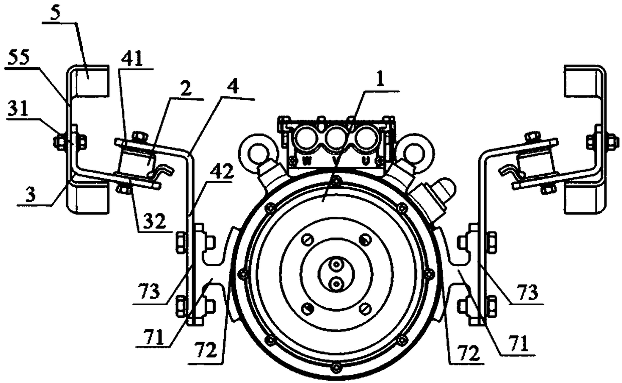
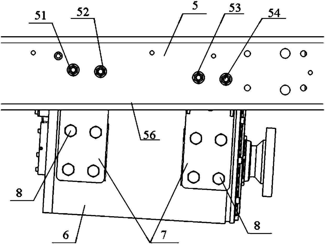
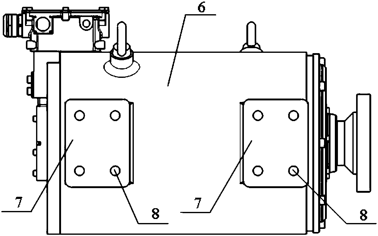
[0031] Such as figure 1 , figure 2 , image 3 , Figure 4 , Figure 5 As shown, a driving motor suspension structure includes a driving motor 1, a vehicle frame 5, a shock-absorbing rubber pad 2, a suspension bracket 3 for installing the driving motor 1 on the vehicle frame 5, and a s...


PUM


Abstract

The invention discloses a driving motor suspension structure and an installation method thereof. The suspension structure comprises a driving motor, a frame, a shock-absorption rubber pad, a mount bracket, and a mounting bracket; the mount bracket is used for driving the motor to install on the frame, and the mounting bracket is used for connecting with the driving motor; and one end of the shock-absorption rubber pad is connected with the mount bracket, and the other end of the shock-absorption rubber is connected with the mounting bracket. Two sides of the middle end of a shell of the driving motor are separately provided with installation a convex platform, and the installation convex platforms are of an I-shaped structure. A plurality of mounting holes with relative angles and not in the same level are arranged on the frame to enable the structures of the mount bracket and the mounting bracket to be simple, and all factors which can cause the mount bracket and the mounting bracketto be irregular are transferred to different hole site coordinates of the mounting holes of the frame. The installation method of the driving motor suspension structure comprises the steps that 1, theshock-absorption rubber pad is separately fixed on the mount bracket and the mounting bracket with nuts; 2, the mount bracket, the shock-absorption rubber pad and the mounting bracket which are assembled together are installed on the frame; and 3, the driving motor is installed.

Description

technical field [0001] The invention belongs to the technical field of automobiles, and in particular relates to a drive motor suspension structure and an installation method thereof. Background technique [0002] The electric light truck is powered by the drive motor, because the maximum torque of the drive motor is large, the speed is fast, and the electric light truck does not have a transmission device. If the shock absorption and buffering effect of the drive motor cannot be guaranteed when the drive motor is working, it will easily affect the normal operation of the electric light truck. Therefore, it is necessary to design a good suspension structure of the electric light truck drive motor, so as to play a certain role in shock absorption and buffering for the electric light truck drive motor, and ensure the normal supply of electric light truck power. In addition, the existing drive motor mounting bracket and drive motor suspension bracket have complex structures, a...

Claims


Application Information

Patent Timeline
Patent Type & Authority Applications(China)
IPC IPC(8): B60K1/00
CPCB60K1/00
Inventor 贾贯举唐庆伟郭志强贾钊
Owner CHERY COMML VEHICLE ANHUI
Why Eureka
Try Eureka