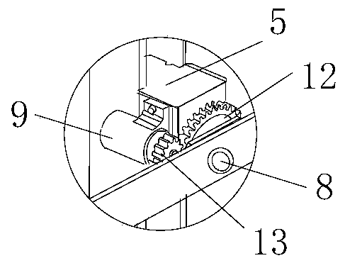
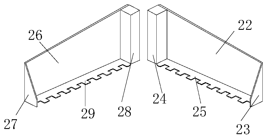
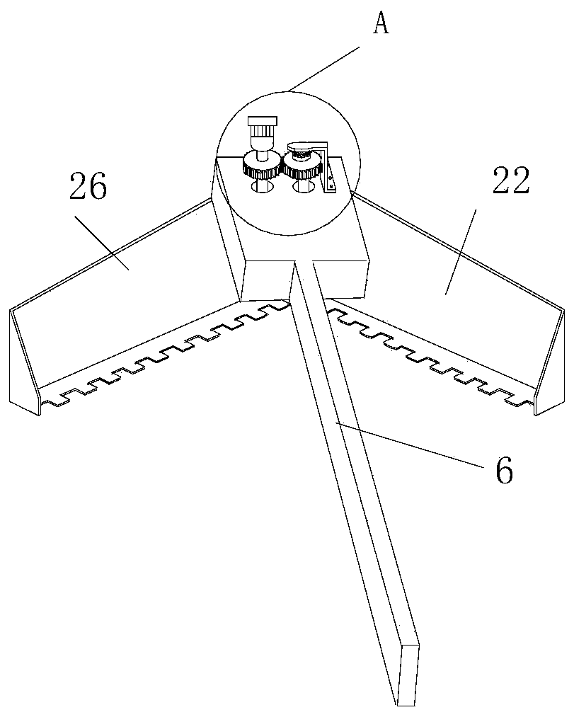
A slag removal machine

A kind of technology of slag fishing machine and slag plate

Active Publication Date: 2020-01-21
贵港沃斯顿科技有限公司
View PDF2 Cites 0 Cited by
  • Summary
  • Abstract
  • Description
  • Claims
  • Application Information

AI Technical Summary

Problems solved by technology

Existing furnace slag removal sometimes requires workers to carry out highly dangerous and close-distance furnace operations. At the same time, the scum has high adhesion, is not easy to fall off, and has low efficiency. It will also cause waste of molten steel and reduce economic benefits.
Even if the slag grab is used, it is not resistant to high temperature and requires frequent replacement of the grab, which increases the cost
However, the existing slag removal machine has a complex structure, large volume, high price, and the slag removal support is fixed, and the depth of the slag removal machine submerged in the furnace is constant, which cannot meet the requirements of the slag removal production process.

Method used


Image

  • A slag removal machine
  • A slag removal machine
  • A slag removal machine

Examples


Embodiment Construction

[0023] The technical solutions of the present invention will be clearly and completely described below in conjunction with the accompanying drawings. Apparently, the described embodiments are part of the embodiments of the present invention, but not all of them. Based on the embodiments of the present invention, all other embodiments obtained by persons of ordinary skill in the art without making creative efforts belong to the protection scope of the present invention. In the description of the present invention, it should be noted that the orientation or positional relationship indicated by the terms "upper", "lower", "left", "right", "inner" and "outer" are based on the Orientation or positional relationship is only for the convenience of describing the present invention and simplifying the description, and does not indicate or imply that the referred device or element must have a specific orientation, be constructed and operated in a specific orientation, and thus should not...


PUM


Abstract

The invention belongs to the technical field of metal smelting equipment. The slag fishing machine comprises a supporting base, wherein a rotary disk is arranged on the supporting base, a sliding railis vertically fixed to the rotary disk; the slag fishing machine further comprises a first motor fixed to the supporting base, a first transmission mechanism connected between the first motor and therotary disk and a sliding block seat which is arranged on the sliding rail and can slide along the sliding rail; the slag fishing machine further comprises a slag fishing arm, a slag fishing claw isarranged at the front end of the slag fishing arm, the tail end of the slag fishing arm is in rotatable connection with the sliding block seat through a first rotating shaft which is horizontally arranged, a second motor is fixed to the sliding block seat, and a second transmission mechanism is connected between the second motor and the first rotating shaft. The slag fishing machine disclosed by the invention has the advantages of simple structure, ability in effectively improving a slag fishing efficiency and ability in meeting a slag fishing production technology.

Description

technical field [0001] The invention belongs to the technical field of metal smelting equipment, and in particular relates to a slag removing machine. Background technique [0002] The water quenching process in the copper smelting industry uses water flow to cool the copper liquid in the molten state. When the copper liquid solidifies, it will burst into fine copper slag. This copper slag is called matte. The copper slag produced by the bursting It will be scattered in the water quenching pool, so a slag removal machine is needed to collect and salvage the copper slag so that it can enter the next smelting process. Existing slag removal from furnaces sometimes requires workers to carry out highly dangerous and close-range furnace operations. At the same time, scum has high adhesion, is not easy to fall off, and has low efficiency. It will also cause waste of molten steel and reduce economic benefits. Even if the slag grab is used, it is not resistant to high temperature an...

Claims


Application Information

Patent Timeline
Patent Type & Authority Patents(China)
IPC IPC(8): C22B15/00B22D43/00
CPCB22D43/00C22B15/0026
Inventor 林天华
Owner 贵港沃斯顿科技有限公司
Why Eureka
Try Eureka