

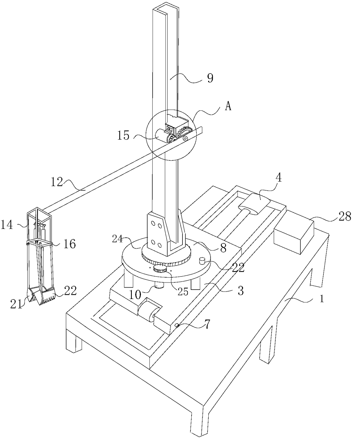
Liquid ironslag extractor
A slag removal machine and molten iron technology, applied in the field of iron and steel metallurgy, can solve the problems of low slag removal efficiency, adverse effects on production, and inability to meet the needs of iron and steel metallurgy production, and achieve improved slag removal efficiency, slag removal speed and slag removal quality , The effect of fast and efficient automatic slag removal
- Summary
- Abstract
- Description
- Claims
- Application Information
AI Technical Summary
Problems solved by technology
Method used
Image

Examples
Embodiment Construction
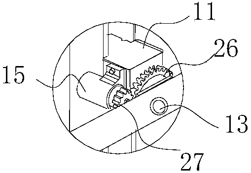
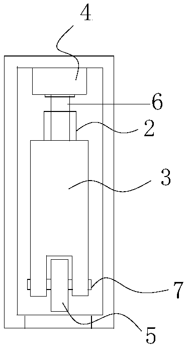
[0022] The technical solutions of the present invention will be clearly and completely described below in conjunction with the accompanying drawings. Apparently, the described embodiments are some of the embodiments of the present invention, but not all of them. Based on the embodiments of the present invention, all other embodiments obtained by persons of ordinary skill in the art without making creative efforts belong to the protection scope of the present invention. In the description of the present invention, it should be noted that the orientation or positional relationship indicated by the terms "upper", "lower", "inner", "outer" and the like are based on the orientation or positional relationship shown in the accompanying drawings, and are only for It is convenient to describe the present invention and simplify the description, but does not indicate or imply that the device or element referred to must have a specific orientation, be constructed and operate in a specific ...
PUM
 Abstract
Description
Claims
Application Information