Full-automatic pipe fitting machining equipment

A processing equipment, fully automatic technology, applied in metal processing equipment, metal processing, metal processing mechanical parts, etc., can solve the problems of troublesome processing, low efficiency, inconvenient U-turn, etc.

Active Publication Date: 2021-09-28
江苏泰源数控机床有限公司
View PDF16 Cites 0 Cited by
  • Summary
  • Abstract
  • Description
  • Claims
  • Application Information

AI Technical Summary

Problems solved by technology

It is relatively easy to turn around for short workpieces, but it is very inconvenient for long workpieces, and manual U-turns are often required, which seriously affects the processing efficiency
Therefore, the pipe fitting processing device in the prior art cannot realize the automatic entry and exit of pipe fittings, the processing process is cumbersome, the workload is large, and the efficiency is low

Method used


Image

  • Full-automatic pipe fitting machining equipment
  • Full-automatic pipe fitting machining equipment
  • Full-automatic pipe fitting machining equipment

Examples


Embodiment Construction

[0027] The present invention will be described in detail below in conjunction with the accompanying drawings and specific embodiments.

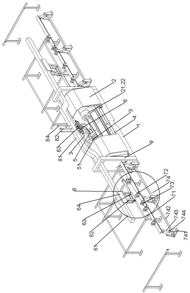
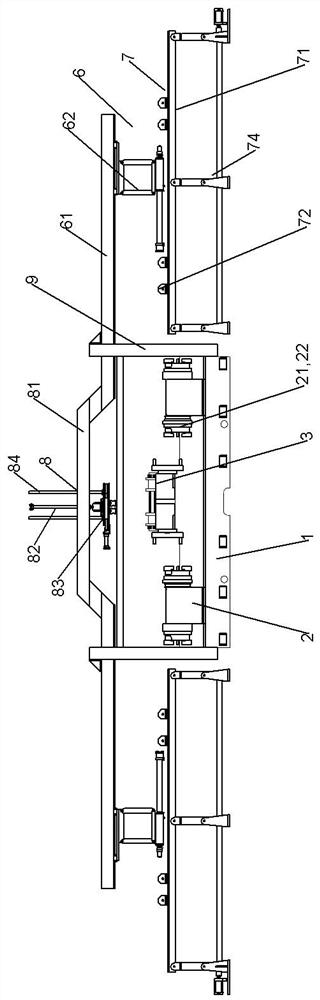
[0028] A fully automatic processing equipment for pipe fittings according to an embodiment of the present invention is as follows: Figure 1 to Figure 3 As shown, the fully automatic processing equipment for pipe fittings in this embodiment includes a machine tool 1, a spindle housing 2 with a spindle 21 inside, and an electric tool holder 3 for processing workpieces. The end of the spindle 21 is provided with a The clamping mechanism 22, the clamping mechanism 22 adopts a pneumatic chuck.

[0029] The first carriage 4 and the second carriage 5 are slidably mounted on the machine tool 1, and the spindle housing 2 and the first carriage 4 are two, and the two spindle housings 2 are symmetrically installed on two sides respectively. On the first carriage 4, the first carriage 4 drives the main shaft housing 2 to slide axially along the main sh...


PUM


Abstract

The invention discloses full-automatic pipe fitting machining equipment. The equipment comprises a machine tool, spindle box bodies and an electric tool rest, wherein spindles are arranged inside the spindle box bodies, and the electric tool rest is used for machining workpieces. Clamping mechanisms which are used for clamping the workpieces are arranged at the ends of the spindles, two first pull plates and a second pull plate are assembled on the machine tool in a sliding mode, and the two spindle box bodies and the two second pull plates are arranged. The two spindle box bodies are installed on the two first pull plates in a left-and-right symmetry mode, the first pull plates drive the spindle box bodies to slide in the axial direction of the spindles, the spindles of the two spindle box bodies are located on the same straight line, and the clamping mechanisms on the spindles of the two spindle box bodies are close to each other to clamp the two ends of each workpiece respectively. The second pull plate drives the electric tool rest to slide in the direction of being perpendicular to the axial direction of the spindles, material frames are symmetrically arranged on the left side and the right side of the first pull plate, and each material frame comprises a short workpiece material frame located on the upper portion and a long workpiece material frame located on the lower portion. The long workpiece material frames and the short workpiece material frames feed the long and short workpieces into the spindle box bodies to be machined and send the long and short workpieces out of the spindle box bodies respectively.

Description

technical field [0001] The invention relates to a fully automatic processing equipment for pipe fittings, which belongs to the technical field of pipe fitting processing equipment. Background technique [0002] Gun barrels are commonly used pipe fittings on oil and gas wells, and are in great demand. The commonly used machining methods are relatively single, cumbersome, heavy workload and low efficiency. The pipe fitting processing device in the prior art usually includes a machine tool and a spindle box and an electric tool rest arranged on the machine tool. The spindle box is provided with a spindle, and the end of the spindle is provided with a clamping mechanism for clamping the pipe. The pipe fittings are clamped by the holding mechanism, and the pipe fittings are processed by the cutter head on the electric tool holder. When both ends of the pipe need to be processed, the pipe needs to be turned around after processing one end so that the processed end is fixed on the...

Claims


Application Information

Patent Timeline
Patent Type & Authority Applications(China)
IPC IPC(8): B23Q7/05B23Q3/06
CPCB23Q7/055B23Q3/064
Inventor 蔡宝玉叶晶苏文成刘勤
Owner 江苏泰源数控机床有限公司
Why Eureka
Try Eureka