Fabricated building steel beam wing plate automatic locking device

A technology for building steel, beam and wing panels, applied in the directions of auxiliary devices, auxiliary welding equipment, welding/welding/cutting items, etc., which can solve the problems of wing plate deflection, wing plate and web jumping, and cost increase.

Pending Publication Date: 2021-10-22
ZHIMAIDE CO LTD
View PDF8 Cites 0 Cited by
  • Summary
  • Abstract
  • Description
  • Claims
  • Application Information

AI Technical Summary

Problems solved by technology

First, its clamping force on the wing plate comes from the thrust of the opening and closing drive cylinder. Only when the thrust of the opening and closing drive cylinder reaches a certain level, the friction force generated by the clamping force is sufficient to overcome the reaction of the web. To realize the clamping and fixing of the wing plate, which forms a higher requirement for the thrust of the opening and closing drive cylinder; and when clamping and fixing the large thickness wing plate, it is often necessary to replace the oil cylinder with a larger thrust. Normal clamping and fixing can be realized; therefore, the flap stopper has poor adaptability to flaps of different thicknesses, and the cost is relatively high
Second, during the clamping and fixing process of the opening and closing drive cylinder, there will be simultaneous use of the clamping drive cylinder and the slider drive cylinder in the web clamping and dragging device. The simultaneous function of the three cylinders requires sufficient pressure supply capacity Pumping station support, which will virtually increase the requirements for pumping stations and further increase the cost
The third is that the sequence of the actions of the two stop clamping arms is uncontrollable. When clamping the wing plate, there is often a situation where the lower stop clamping arm hits the wing plate first, which will cause the wing plate and the web to jump , and even lead to the deflection of the wing plate, which affects the end alignment effect
To sum up, the effect of the above-mentioned wing plate stop device is far from satisfactory, and further improvement is needed

Method used


Image

  • Fabricated building steel beam wing plate automatic locking device
  • Fabricated building steel beam wing plate automatic locking device
  • Fabricated building steel beam wing plate automatic locking device

Examples


Embodiment Construction

[0017] Below in conjunction with accompanying drawing and embodiment, further elaborate the present invention. In the following detailed description, exemplary embodiments of the present invention are described by way of illustration only. Needless to say, those skilled in the art would realize that the described embodiments can be modified in various different ways, all without departing from the spirit and scope of the present invention. Accordingly, the drawings and description are illustrative in nature and not intended to limit the scope of the claims.

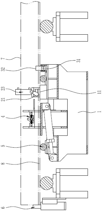
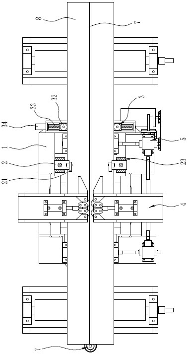
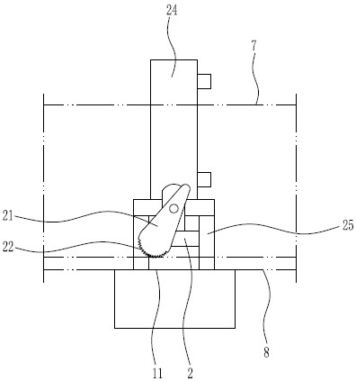
[0018] Such as figure 1 , figure 2 and image 3 As shown, the prefabricated building steel girder wing automatic locking device includes a locking base 1, and the locking base 1 can be set integrally with the base of the web clamping and dragging device 4, or it can be set separately with the web The base of the clamping and dragging device 4 is relatively fixed, and this embodiment is illustrated as an integral arra...


PUM


Abstract

The invention discloses a fabricated building steel beam wing plate automatic locking device. The device comprises a locking base, a wing plate supporting table is arranged on the locking base, wheel locking seats are installed on the two sides, in the wing plate conveying direction, of the locking base correspondingly, locking cams located above the wing plate supporting table are rotationally installed on the wheel locking seats correspondingly, and a locking height limiter is arranged between each wheel locking seat and the locking base. When wing plates move reversely, the locking cams can rapidly swing reversely, and the wing plates are reliably and rigidly clamped and fixed. In the whole locking process, a high-thrust oil cylinder is not used, the oil pressure requirement is low, the cost is low, collision is avoided in the using process, and smooth end alignment is facilitated. When the ends of the wing plates with different thicknesses are aligned, the locking height limiters only need to be used for adaptively adjusting the height of the locking cams, and the fabricated building steel beam wing plate automatic locking device can adapt to reliably locking the wing plates of different thicknesses.

Description

technical field [0001] The invention relates to the technical field of welding of building steel beams, in particular to an automatic locking device for assembled building steel beam wing plates. Background technique [0002] Welding and forming construction steel girders are becoming more and more popular due to their flexibility in cross-section and thickness. For example, the construction steel girder of H-shaped steel is generally welded to form T-shaped steel after the web is welded to the first wing plate, and then the T-shaped steel is turned over and welded with the second wing plate to form H-shaped steel. Pre-assembly and end alignment are required before the web is welded to the first wing and before the T-shaped steel is welded to the second wing. For example, the utility model patent with the application number "201921474874.5" and the name "Section Steel End Alignment Automatic Adjustment Device" uses the alignment limit device to detect the end faces of the w...

Claims


Application Information

Patent Timeline
IPC IPC(8): B23K37/04B23K101/28
CPCB23K37/0443B23K2101/28
Inventor 张兆瑞杨椿曲秀华刘新冬
Owner ZHIMAIDE CO LTD
Why Eureka
Try Eureka