A smart card cleaning device capable of cleaning upper and lower cleaning rollers

A cleaning device and smart card technology, applied in cleaning methods and appliances, cleaning methods using tools, chemical instruments and methods, etc., can solve the problems of cleaning rollers that cannot be cleaned, poor cleaning effect of cards, etc., and achieve the effect of improving conveying efficiency

Inactive Publication Date: 2017-11-24
GUANGZHOU MINGSEN TECH CO LTD
View PDF8 Cites 1 Cited by
  • Summary
  • Abstract
  • Description
  • Claims
  • Application Information

AI Technical Summary

Problems solved by technology

[0004] The existing smart card cleaning devices generally have the following disadvantages: usually only the upper cleaning roller can be cleaned, and the lower cleaning roller cannot be cleaned, which makes the cleaning effect of the card poor

Method used


Image

  • A smart card cleaning device capable of cleaning upper and lower cleaning rollers
  • A smart card cleaning device capable of cleaning upper and lower cleaning rollers
  • A smart card cleaning device capable of cleaning upper and lower cleaning rollers

Examples


Embodiment 1

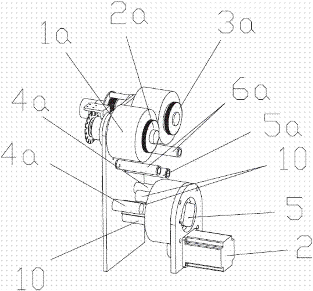
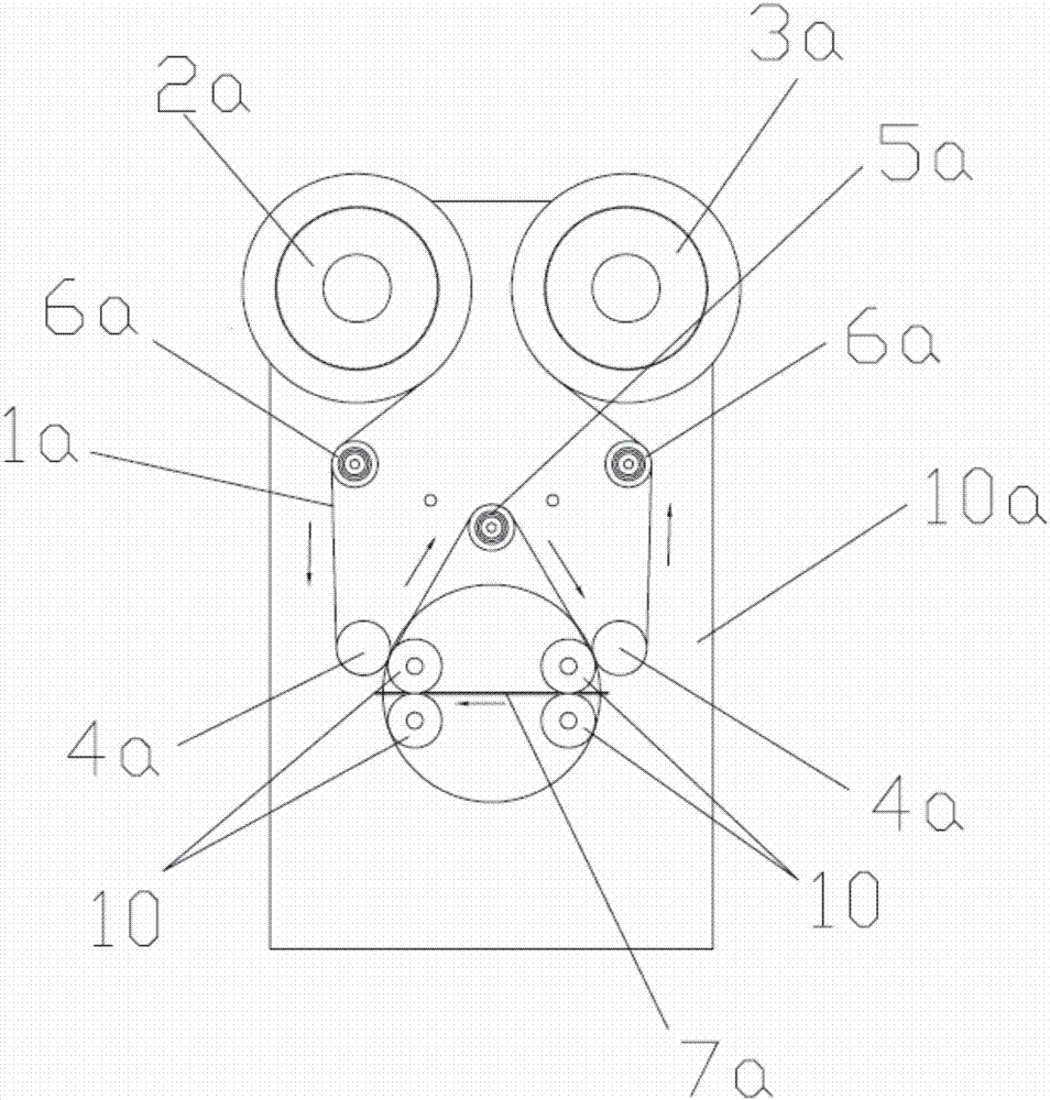
[0038] see Figure 1 ~ Figure 4 The smart card cleaning device that can clean the upper and lower cleaning rollers of the present invention includes a frame 10a, a dust removal mechanism on the card surface, and a cleaning belt conveying mechanism, wherein the cleaning belt conveying mechanism includes a cleaning belt 1a, an unused cleaning belt rewinding wheel 2a , Used cleaning belt rewinding wheel 3a, guide wheel group and rewinding power mechanism.

[0039] The card surface dust removal mechanism includes a fixed frame 1, two sets of cleaning rollers, an overturning power mechanism for driving the two sets of cleaning rollers to rotate as a whole, and a card conveying power for driving the rotation of each cleaning roller 10 in the two sets of cleaning rollers. mechanism, each group of cleaning rollers includes two pairs of cleaning rollers 10, and the card conveying power mechanism is arranged on the turning part of the turning power mechanism; the rotation center of the ...

Embodiment 2

[0054] The difference between this embodiment and embodiment 1 is that in this embodiment:

[0055] see Figure 8, the transmission mechanism includes four transmission gears 15 and a synchronous belt transmission mechanism 16, wherein each cleaning roller 10 is coaxially connected with a transmission gear 15 respectively, and two transmission gears 15 in a group of cleaning rollers are meshed; The main shaft of the card feeding motor 5 is connected with one of the cleaning rollers 10 in one group of cleaning rollers to form a power roller, which cleans with one of the other cleaning rollers through the synchronous belt transmission mechanism 16. Roller 10 is connected.

Embodiment 3

[0057] The difference between this embodiment and Embodiment 1 is that in the compression control mechanism of this embodiment:

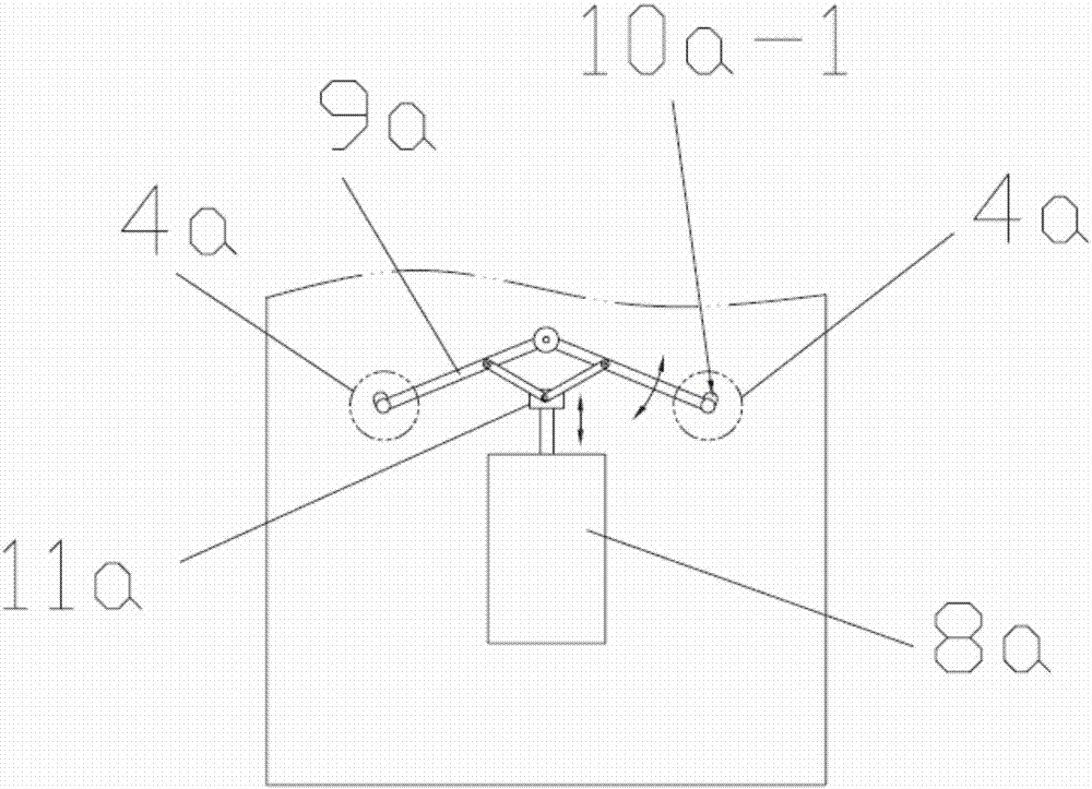
[0058] see Figure 9 ~ Figure 12 , the transmission mechanism includes two rotating arms 11a, one end of the two rotating arms 11a is connected to a cleaning belt pressing wheel 4a, the middle part is connected to the frame 10a through a rotatable structure, and the other end is provided with some gears that mesh with each other 11a-1; the power mechanism is a rotation drive mechanism that pushes one of the rotation arms 11a to rotate.

[0059] see Figure 9 ~ Figure 12 , the power mechanism is composed of an electromagnet 12a, the outer end of the armature 13a of the electromagnet 12a is connected to one of the rotating arms 11a through a swing rod 14a, and a spring 15a is provided on the armature 13a. Its working principle is: under normal conditions, the electromagnet 12a is in a de-energized state, under the action of the spring 15a, the armat...


PUM


Abstract

The invention discloses an intelligent card cleaning device capable of cleaning upper cleaning wheels and lower cleaning wheels. The intelligent card cleaning device comprises a card face dust removing mechanism and a cleaning belt conveying mechanism. The card face dust removing mechanism comprises a fixing frame, two cleaning wheel sets, an overturning power mechanism driving the two cleaning wheel sets to integrally rotate, and a card conveying power mechanism used for driving the cleaning wheels in the two cleaning wheel sets to rotate by themselves. Each cleaning wheel set comprises two paired cleaning wheels. A guiding wheel set comprises two cleaning belt pressing wheels arranged on the outer sides of the two cleaning wheels located at the upper portion. A cleaning belt is pressed on the two cleaning wheels located at the upper portion through the two cleaning belt pressing wheels. The two cleaning belt pressing wheels are connected with a pressing control mechanism. The cleaning device can clean the upper cleaning wheels and the lower cleaning wheels, and normal card conveying is not affected when any cleaning wheel is cleaned.

Description

technical field [0001] The invention relates to smart card manufacturing equipment, in particular to a smart card cleaning device. Background technique [0002] In the production process of smart cards, it is necessary to write relevant information on the surface of the card, such as writing text or pattern information on the card surface through flat printing, embossed coding, laser coding, etc. In an open production environment, the surface of the card is prone to dust and other impurities. Therefore, the card surface needs to be cleaned before surface information processing. [0003] The existing smart card cleaning device is mainly composed of a card surface dust removal mechanism, a cleaning belt conveying mechanism and a cleaning belt tensioning mechanism, wherein the card surface dust removal mechanism is mainly composed of pairs of cleaning rollers, and the card to be cleaned is moved from The cleaning rollers pass between the cleaning rollers, and the dust on the c...

Claims


Application Information

Patent Timeline
Patent Type & Authority Patents(China)
IPC IPC(8): B08B1/02B08B7/00
CPCB08B1/02B08B7/0028
Inventor 王开来
Owner GUANGZHOU MINGSEN TECH CO LTD
Why Eureka
Try Eureka