Following mechanism used during spiral welding pipe cutting and operation method of mechanism

A technology of spiral welded pipe and pipe cutting, which is applied in the direction of pipe shearing device, shearing device, and the attachment of shearing machine, etc., which can solve the problems of increasing waste pipe rate, delay or resistance, etc., and achieve the improvement of pipe cutting yield and weight Lightweight, simple and compact overall structure

Active Publication Date: 2016-06-08
中冶辽宁德龙钢管有限公司
View PDF6 Cites 1 Cited by
  • Summary
  • Abstract
  • Description
  • Claims
  • Application Information

AI Technical Summary

Problems solved by technology

However, in the accompanying mechanism using the electro-hydraulic push rod as the power, due to factors such as the ambient temperature and the characteristics of the hydraulic oil used, the thrust of the electro-hydraulic push rod has a small amount of change, which can easily cause delay or stagnation, directly increasing waste pipe rate

Method used


Image

  • Following mechanism used during spiral welding pipe cutting and operation method of mechanism
  • Following mechanism used during spiral welding pipe cutting and operation method of mechanism
  • Following mechanism used during spiral welding pipe cutting and operation method of mechanism

Examples


Embodiment Construction

[0021] The specific embodiment of the present invention will be further described below in conjunction with accompanying drawing:

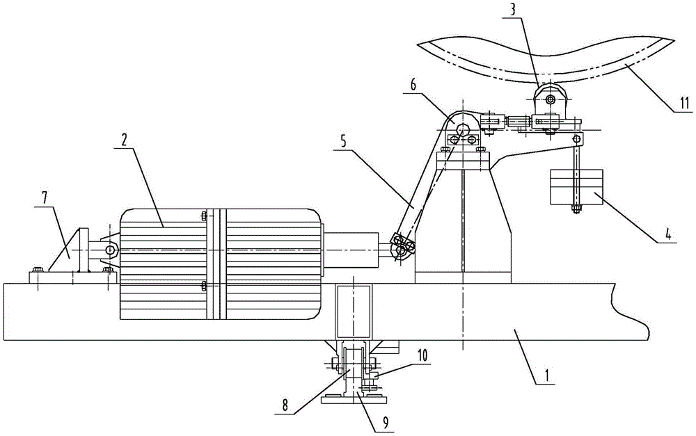
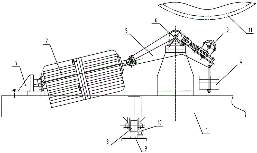
[0022] Such as Figure 1-Figure 2 Shown is a structural schematic diagram of the accompanying mechanism when a spiral welded pipe is cut according to the present invention. An accompanying mechanism for spiral welded pipe cutting according to the present invention includes an accompanying platform 1, an electro-hydraulic push rod 2, an L-shaped swing arm 5, a cutter wheel 3 and a weight 4, and a traveling wheel 8 is arranged at the bottom of the accompanying platform 1 , can drive the accompanying platform 1 to walk along the track parallel to the conveying direction of the spiral welded pipe 10; Its hinge point is higher than the electro-hydraulic push rod 2; the two ends of the L-shaped swing arm 5 are suspended in the air, and one end is hinged with the extended end of the electro-hydraulic push rod 2, and the upper part of the other end is pr...


PUM


Abstract

The invention relates to a following mechanism used during spiral welding pipe cutting and an operation method of the following mechanism. The following mechanism comprises a following platform, an electric-hydraulic pusher, an L-shaped swing arm, a cutter wheel and a dropping weight. A walking wheel is arranged at the bottom of the following platform and can drive the following platform to walk along a rail parallel to the conveying direction of a spiral welding pipe; the fixed end of the electric-hydraulic pusher is hinged to the following platform, and the middle portion of the L-shaped swing arm is hinged to a support; two ends of the L-shaped swing arm are suspended, one end of the L-shaped swing arm is hinged to the stretching-out end of the electric-hydraulic pusher, the cutter wheel is arranged on the upper portion of the other end of the L-shaped swing arm, and the dropping weight is arranged on the lower portion of the other end of the L-shaped swing arm; and the axis of the cutter wheel is parallel to the axis direction of the spiral welding pipe, and a weight assembly is arranged in the dropping weight and is composed of a plurality of weights with different thickness specifications. The lever principle and the dropping weight capable of adjusting the weight of the weights are used for achieving rapid joint and separation of the following mechanism and the moving spiral steel pipe while the electric-hydraulic pusher and the cutter wheel are adopted to achieve the following action, accuracy and reliability of pipe cutting action are ensured, and the pipe cutting yield is improved greatly.

Description

technical field [0001] The invention relates to the technical field of on-line cutting of spiral welded pipes, in particular to an accompanying mechanism and an operation method for cutting spiral welded pipes. Background technique [0002] During the processing of spiral welded pipe, the steel pipe needs to be cut to length. The pipe cutting device is installed on the accompanying mechanism to realize the pipe cutting action while moving synchronously with the spiral welded pipe, so as to meet the requirements that the cutting track is perpendicular to the steel pipe axis and connected end to end. Online pipe cutting requires that the accompanying mechanism engages and disengages from the steel pipe in a timely and accurate manner without delay or stagnation. However, in the accompanying mechanism using the electro-hydraulic push rod as the power, due to factors such as the ambient temperature and the characteristics of the hydraulic oil used, the thrust of the electro-hyd...

Claims


Application Information

Patent Timeline
Patent Type & Authority Applications(China)
IPC IPC(8): B23D21/00B23D33/00
CPCB23D21/00B23D33/00
Inventor 初春洲薛俊
Owner 中冶辽宁德龙钢管有限公司
Why Eureka
Try Eureka