Support for hole drilling and rebar planting of indoor building top and wall column side face and construction method thereof

A technology for building and planting steel bars, applied in the direction of building structure, building, housing structure support, etc., can solve the problems of construction time lag, inconvenient operation, low construction efficiency, etc., to avoid potential safety hazards and accidents, save time and The effect of physical strength and high construction efficiency

Active Publication Date: 2018-05-29
DARONG CONSTR GROUP
View PDF10 Cites 6 Cited by
  • Summary
  • Abstract
  • Description
  • Claims
  • Application Information

AI Technical Summary

Problems solved by technology

[0002] With the development of civil engineering, the top of indoor buildings, such as ceiling ceiling construction and masonry partition wall construction on the side of wall columns, etc. have also been widely used. Two methods are used, the traditional pre-embedded type, but the pre-embedded type requires drilling to penetrate the formwork, which affects the turnover efficiency of the formwork and slows down the construction progress of the main structure
Later, people adopted the rebar-planting construction method to overcome the above shortcomings, but due to the lag of construction time, the formwork supporting scaffolding has been removed, and it is necessary to re-build mobile scaffolding or herringbone ladders, but even so, there are still drilling tools and materials that need to be carried. It is laborious and time-consuming to frequently go up and down scaffolding or ladders to operate on the frame, especially when drilling with an impact drill or electric hammer, the vibration force is relatively large, and it is difficult for the operator to stand firm and difficult to use when drilling on the frame or ladder. force, there are serious safety hazards, and at the same time affect the drilling quality
In addition, the construction methods of the prior art require frequent up-and-down scaffolding or herringbone ladders for drilling, clearing holes, injecting glue, and planting bars to operate on the frame. The operation is inconvenient, labor-intensive and time-consuming, and the construction efficiency is not high. poor security

Method used


Image

  • Support for hole drilling and rebar planting of indoor building top and wall column side face and construction method thereof
  • Support for hole drilling and rebar planting of indoor building top and wall column side face and construction method thereof
  • Support for hole drilling and rebar planting of indoor building top and wall column side face and construction method thereof

Examples


Embodiment 1

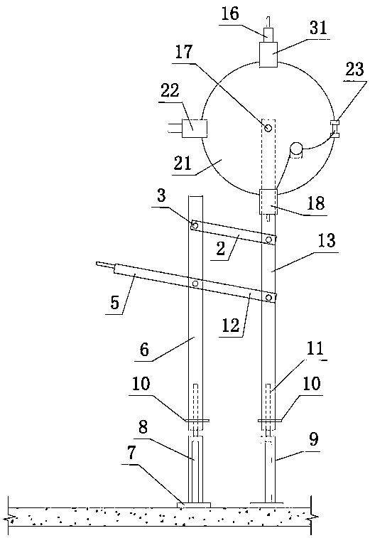
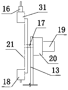
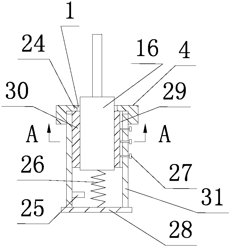
[0039] Such as figure 1 , figure 2 , image 3 , Figure 4 , Figure 5 shown

[0040] The bracket for planting bars on the roof of indoor buildings according to the present invention includes a first column, namely the main column 6, a second dowel bar, namely the force transmission vertical bar 13, and a movable connecting rod hinged with the main column 6 and the force transmission vertical bar 13. Connecting cross bar 2, the first dowel bar 12, which is parallel to connecting cross bar 2 and hinged with main column 6 and force transmission vertical bar 13, is the force transmission bar 12, and the part of force transmission bar 12 extending outside the main column 6 constitutes Operating rod 5, main column 6 and power transmission vertical bar 13 are parallel. Here, the main column 6 is strictly speaking that the upper part of the main column 6 doubles as a fixed connecting rod. The connecting cross bar 2 is on the top, and the force transmission cross bar 12 is on th...

Embodiment 2

[0060] Such as Figure 6 , Figure 7 , Figure 8 , Figure 9 , Figure 10 shown

[0061] The bracket for drilling the reinforcement on the side of the indoor wall column of the present invention includes the first column, namely the front column 45 and the second column, namely the rear column 41, and the fixed connecting rod vertically fixed to the front column 45 and the rear column 41, i.e. the connecting cross bar 39, The second dowel bar parallel to the connection cross bar 39 is the force transmission cross bar 35 , and the force transmission cross bar 35 is located above the connection cross bar 39 . A first dowel bar, that is, the force transmission vertical bar 37 is hinged with the connecting cross bar 39 and the force transmission cross bar 35, and the part of the force transmission vertical bar 37 extending out of the connection cross bar 39 lower side constitutes the operating rod 40, and the front column 45 is connected to the rear Columns 41 are parallel. ...


PUM


Abstract

The invention discloses a support for hole drilling and rebar planting of indoor building top and wall column side face and a hole drilling and rebar planting construction method thereof. The supportcomprises a first upright, a second upright and a four-connection-rod mechanism, and a tool mounting device is arranged at the end, close to the building top and the wall column side face, of a secondforce transmission rod; a turnplate a structure driving the turnplate to rotate and a structure enabling the turnplate to be located at a preset position are arranged at the end, close to the building top and the wall column side face, of the second force transmission rod, and a drilling tool mounting device, an electric air blower mounting device, a glue injector mounting device and a pneumaticfinger for mounting and rebar planting are sequentially and equally fixed at the edge of the turnplate along the circumference. The support is convenient to operate and high in construction efficiencyand safety. By adopting the support and the construction method, hole drilling, cleaning of dust in holes, glue injecting and rebar planting can be performed on the ground, so that time and physicalpower of operating personnel for getting on and off an operation frame or a herringbone ladder are saved in the whole process, and potential safety hazards and accidents caused by hole drilling operation on the frame or the ladder are avoided; the support is convenient to operate and high in construction efficiency and safety.

Description

technical field [0001] The invention relates to the technical field of civil engineering construction, in particular to a bracket for drilling and planting reinforcement on the top of an indoor building and the side of a wall column and a construction method for drilling and planting reinforcement using the bracket. Background technique [0002] With the development of civil engineering, the top of indoor buildings, such as ceiling ceiling construction and masonry partition wall construction on the side of wall columns, etc. have also been widely used. Two methods are used, the traditional pre-embedded type, but the pre-embedded type requires drilling to penetrate the formwork, which affects the turnover efficiency of the formwork and slows down the construction progress of the main structure. Later, people adopted the rebar-planting construction method to overcome the above shortcomings, but due to the lag of construction time, the formwork supporting scaffolding has been r...

Claims


Application Information

Patent Timeline
Patent Type & Authority Applications(China)
IPC IPC(8): E04G1/24E04G1/15E04G1/32
CPCE04G1/15E04G1/24E04G1/32Y02P60/21
Inventor 李辉陈云杰吴洪波徐新强郑剑峰
Owner DARONG CONSTR GROUP
Why Eureka
Try Eureka