Liftable chimney used for garbage incinerator

A technology for waste incinerators and chimneys, applied in incinerators, combustion methods, combustion types, etc., can solve the problems of the old chimneys with single function, large use space, and chimneys occupying a large vertical height, so as to reduce pollution and prolong service life. , to achieve the effect of pollution-free emissions

Inactive Publication Date: 2018-05-29
徐际华
View PDF0 Cites 0 Cited by
  • Summary
  • Abstract
  • Description
  • Claims
  • Application Information

AI Technical Summary

Problems solved by technology

[0004] The object of the present invention is to provide a kind of liftable chimney for garbage incinerator, by setting the liftable chimney on the end side of the exhaust pipe of garbage incinerator, lifting device, support plate, clamp, first chimney, second chimney Cooperate with the structure to realize the lifting of the chimney, which solves the problem that the existing chimney occupies a large vertical height, has a large use space, and has a single function of the old chimney

Method used


Image

  • Liftable chimney used for garbage incinerator
  • Liftable chimney used for garbage incinerator
  • Liftable chimney used for garbage incinerator

Examples


specific Embodiment 1

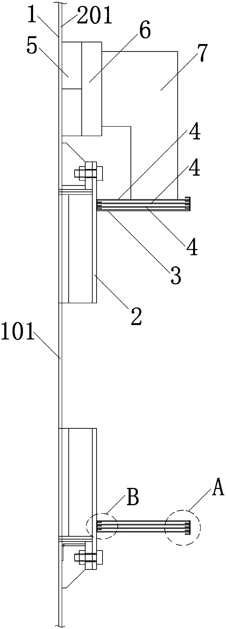
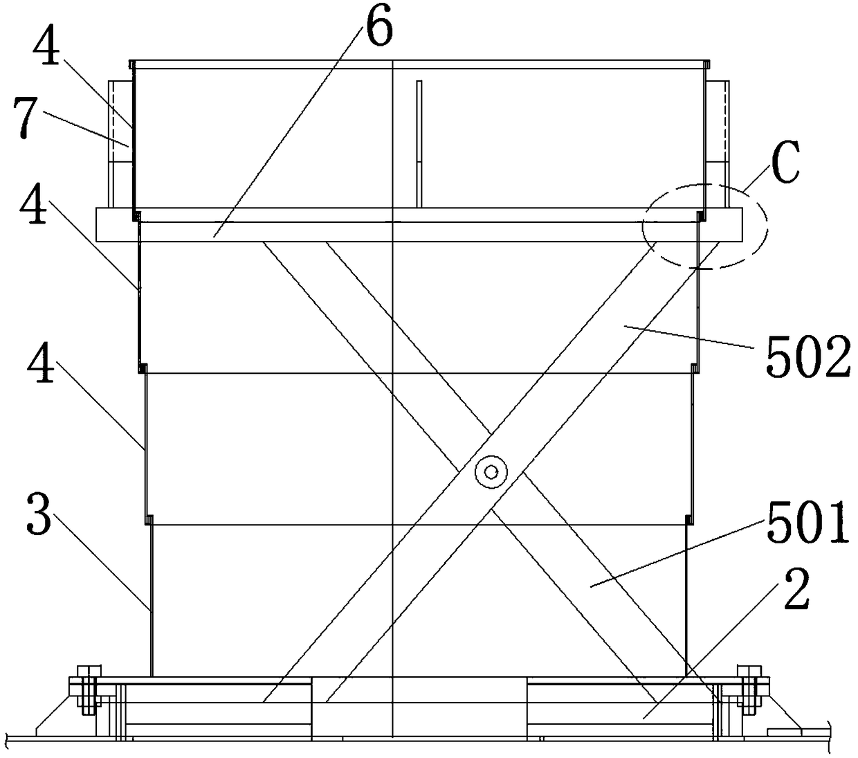
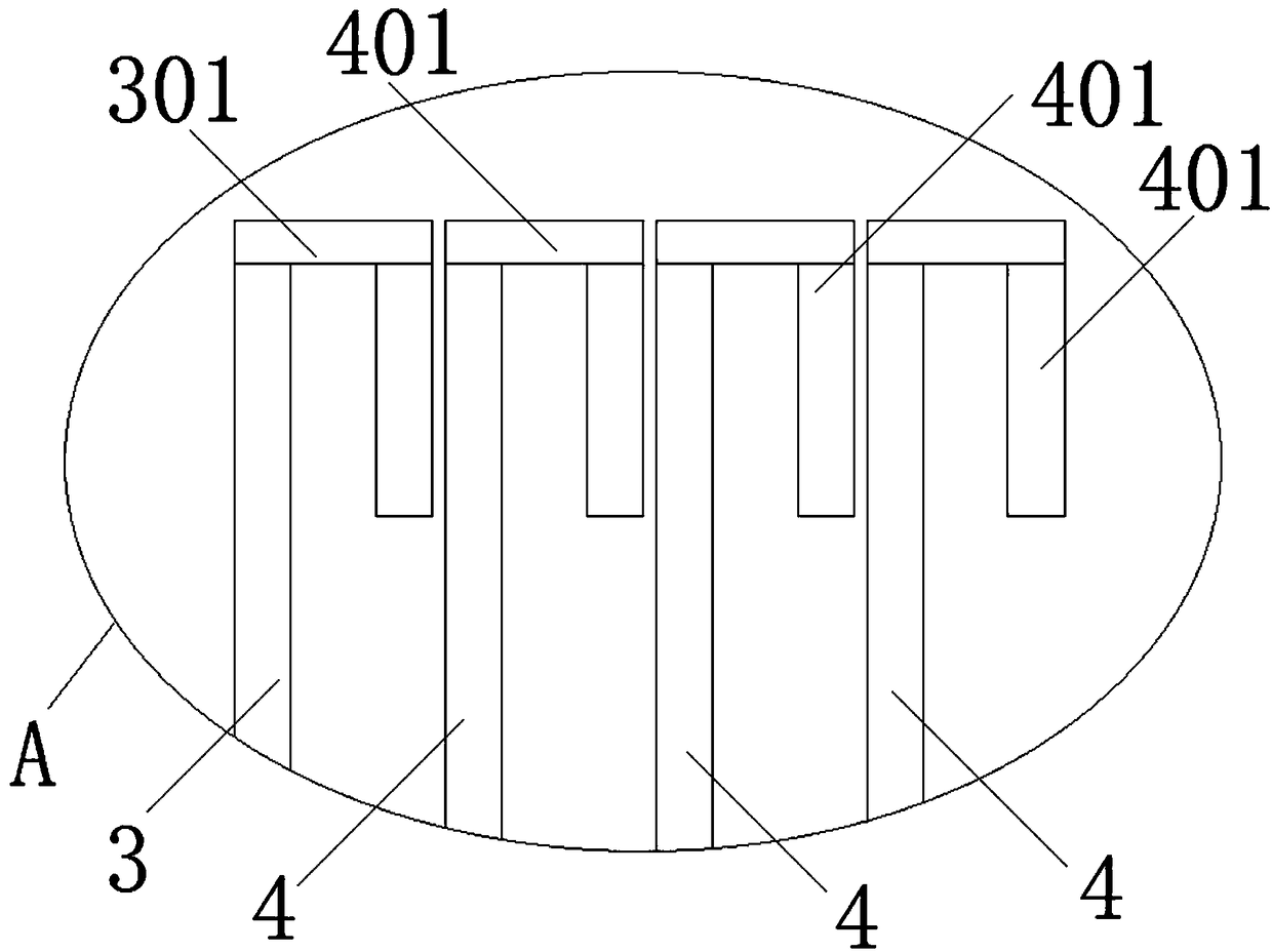
[0029] Such as figure 2 As shown, three second chimneys 4 are used, and the first chimney 3 and the second chimney 4 are all cylindrical cylinders or prismatic cylinders. The first chimney 3 and the three second chimneys 4 are sequentially socketed together. The "X"-shaped lifting device 5 raises the support plate 6, and the clamp 7 fixed on the support plate 6 drives the second chimney 4 on the outermost circle to rise, and the height of the chimney becomes higher, which improves the requirements for flue gas emission and realizes No pollution discharge.

specific Embodiment 2

[0030] Such as Figure 8 As shown, three second chimneys 4 are adopted, and the first chimney 3 and the second chimney 4 both adopt a conical cylinder or a conical cylindrical cylinder, and the first chimney 3 and the three second chimneys 4 are sequentially socketed together, The support plate 6 is raised by the "X"-shaped lifting device 5, and the clamp 7 fixed on the support plate 6 drives the second chimney 4 on the outermost circle to rise, the height of the chimney becomes higher, and the requirements for flue gas emission are improved. Realize pollution-free discharge.

[0031] Preferred:

[0032] Five or six or seven second chimneys 4 are adopted, the first chimney 3 and the second chimney 4 all adopt a conical cylinder or a conical cylindrical cylinder, and the first chimney 3 and five or six or seven second chimneys Two chimneys 4 are socketed together successively; Or adopt five or six or seven second chimneys 4, the first chimney 3, the second chimney 4 all adopt...


PUM


Abstract

The invention discloses a liftable chimney used for a garbage incinerator, and relates to the technical field of garbage incinerators. The liftable chimney comprises an incinerator body, a first baseplate is fixed to the furnace body, and a first chimney body is fixed to the first base plate; the position of the first chimney body and the position of a fume exhaust cylinder are matched and correspond to each other; a first limiting ring is arranged on one end side of the first chimney body, and the first chimney body is sequentially connected with a plurality of second chimney bodies in a sleeved mode; a clamping hoop is fixed to the circumferential side of the second chimney body on the outermost ring; the clamping hoop is fixed to one surface of a supporting plate; and a lifting deviceis arranged on the other surface of the supporting plate. According to the liftable chimney used for the garbage incinerator, the lifting device, the supporting plate, the clamping hoop, the first chimney body and the second chimney bodies are arranged and matched structurally, rising and falling of the liftable chimney are achieved, the vertical height and the using space of the liftable chimneyare adjusted through the lifting device, so that fume gas in a fume emission pipeline remains for a period of time under the required environment and then is emitted, the requirements of flue gas emission are improved, non-pollution emission is achieved, and pollution of garbage incineration fume gas to the environment is reduced.

Description

technical field [0001] The invention belongs to the technical field of garbage incinerators, in particular to a liftable chimney for garbage incinerators. Background technique [0002] At present, waste treatment technologies are basically divided into incineration, sanitary landfill, composting, and waste recycling. Among the conventional waste treatment technologies, incineration has the advantages of obvious reduction effect, complete harmlessness, small land occupation, utilization of waste heat, and reduction of secondary pollution. It meets the requirements of my country's sustainable development strategy. Waste incineration vehicles are used Incinerate garbage, realize the movement of the incinerator, adapt to the incineration of garbage in various places, and reduce the limitations of garbage treatment. [0003] Existing smoke exhaust devices of waste incinerators generally adopt old-fashioned chimneys, which are vertically arranged on the top of the furnace body of ...

Claims


Application Information

Patent Timeline
Patent Type & Authority Applications(China)
IPC IPC(8): F23G5/44F23J13/00
CPCF23G5/44F23J13/00
Inventor 徐际华
Owner 徐际华
Why Eureka
Try Eureka