
A Method for Compensating the Stress Turns of Fiber Optic Gyroscope Pigtail

A loop and pigtail technology, used in gyroscope/steering sensing equipment, Sagnac effect gyroscopes, instruments, etc., can solve the problem that the stress asymmetry of the loop cannot be effectively improved, and the number of turns per layer cannot be guaranteed. problems such as consistency, stress distribution difference, etc., to achieve good thermal symmetry, good stress distribution symmetry, and flexible use.

Active Publication Date: 2021-05-07
TIANJIN NAVIGATION INSTR RES INST
View PDF4 Cites 0 Cited by
  • Summary
  • Abstract
  • Description
  • Claims
  • Application Information

AI Technical Summary

Problems solved by technology

The optical fiber loops wound by the quadrupole symmetrical winding method have shown to have better temperature characteristics than the original spiral winding method, but there is still a gap between the existing quadrupole symmetrical winding method and the ideal quadrupole symmetry, and it is impossible to guarantee every Consistency of Layer Turns
Even if the ideal symmetry of the geometric length of the ring is guaranteed, there are still differences in the stress distribution of the ring in the symmetrical part. Although it has a good suppression effect on the thermal gradient field, it still cannot effectively offset the phase caused by the stress difference.
[0007] In short, although there are a large number of improved ring winding methods, most of them are improved from the offset of the thermal field distribution of the ring. An effective method to accurately overcome the influence of stress is particularly important

Method used


Image

  • A Method for Compensating the Stress Turns of Fiber Optic Gyroscope Pigtail
  • A Method for Compensating the Stress Turns of Fiber Optic Gyroscope Pigtail

Examples


Embodiment Construction

[0023] The embodiments of the present invention will be described in detail below in conjunction with the accompanying drawings. It should be noted that the embodiments are illustrative, not restrictive, and cannot limit the protection scope of the present invention.

[0024] A method for compensating the number of stress turns of fiber optic gyroscope pigtails, which can adopt any one of the following three technical measures, or any combination of several:

[0025] ⑴. Changing the bending radius of the tail fiber with a specific number of turns to realize the ring stress distribution compensation;

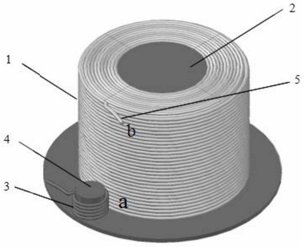
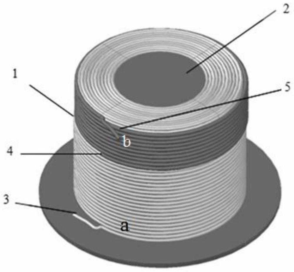
[0026] Change the hoop pigtail stress coil. like figure 1 As shown, the optical fiber ring 1 is disposed on the edge of the ring frame 2 with the fiber pigtail post 4 , and the diameter of the pigtail post 4 is smaller than the inner diameter of the optical fiber ring 1 and is an integer fraction of the inner diameter of the ring 1 . Keep the b-end 5 of the outer layer pigtail ...


PUM


Abstract

The invention relates to a method for compensating the stress turns of the fiber optic gyroscope pigtail. This method adopts three technical measures to perform stress compensation on the pigtail of the multi-pole wound optical fiber ring. The three measures are: ⑴. Change the bending radius of the pigtail with a specific number of turns to realize the compensation of the ring stress distribution; (2) change the winding tension of the pigtail with a specific number of turns to realize the compensation of the stress distribution of the ring; (3) change the colloidal modulus of the pigtail with a specific number of turns to realize the stress distribution of the specific number of turns compensate. In addition to good thermal symmetry, the present invention has better stress distribution symmetry, effectively reduces ring non-reciprocity errors, and better ensures the stability of the fiber optic gyroscope. This compensation method has important application value for improving the temperature and vibration performance of the fiber optic gyroscope.

Description

technical field [0001] The invention relates to the technical field of fiber optic gyroscopes, in particular to a method for compensating the number of stress turns of fiber optic gyroscope pigtails. Background technique [0002] The fiber optic gyroscope is a fiber optic angular rate sensor based on the Sagnac effect, which has the advantages of small size, high precision, all solid state, long service life, and large dynamic range. The strapdown inertial navigation system based on fiber optic gyroscope has been widely used in aerospace, ship navigation and other fields. [0003] As the sensitive core of the fiber optic gyroscope, the performance of the fiber optic ring directly affects the accuracy of the gyroscope. When the environmental factors of the optical fiber loop change, the two beams of light waves propagating in the opposite direction in the optical fiber loop will produce a non-reciprocal phase difference. This non-reciprocal phase shift and the Sagnac phase s...

Claims


Application Information

Patent Timeline
Patent Type & Authority Patents(China)
IPC IPC(8): G01C19/72
CPCG01C19/721G01C19/726
Inventor 刘伯晗杨志怀王玥泽于洪宇
Owner TIANJIN NAVIGATION INSTR RES INST
Learn More