Tiny-particle optical fiber directional driver moving along side polishing and slotting direction and method

A technology of tiny particles and drivers, applied in the optical field, can solve the problems of inflexible operation and single method, and achieve the effect of strong driving direction, simple operation and strong directional driving.

Inactive Publication Date: 2013-02-27
HARBIN ENG UNIV
View PDF0 Cites 0 Cited by
  • Summary
  • Abstract
  • Description
  • Claims
  • Application Information

AI Technical Summary

Problems solved by technology

For example, the waveguide has a single way of transporting tiny particles, and the operation is not flexible enough, etc.

Method used


Image

  • Tiny-particle optical fiber directional driver moving along side polishing and slotting direction and method
  • Tiny-particle optical fiber directional driver moving along side polishing and slotting direction and method
  • Tiny-particle optical fiber directional driver moving along side polishing and slotting direction and method

Examples


Embodiment 1

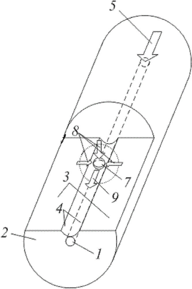
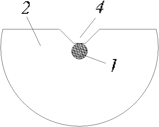
[0038] 1. Polishing and slotting: Take a piece of ordinary single-core optical fiber, and polish and slot one end of the optical fiber to form a figure 1 The side polished slotted fiber shown in the figure should meet the following conditions during the slotting process: (1) the size of the slot can allow tiny particles to pass through smoothly, (2) the distance between the center of the side polished slotted fiber core and the bottom of the slot The distance d satisfies the following relation: d core / 2≤dclad / 2, in this way, a straight single-core side-polished slotted micro-particle directional drive is completed.

[0039] 2. Particle drive: Immerse the prepared straight single-core side-polished slotted optical fiber micro-particle driver in a solution containing a certain amount of micro-particles 7, and after passing through the laser 5, the micro-particles 7 near the slotted area will be captured And directional movement along the slotting direction, such as figure 1 ...

Embodiment 2

[0041] 1. According to the steps in Example 1, a straight single-core side-polished slotted optical fiber micro-particle directional driver is produced;

[0042] 2. Bending the end of the prepared straight single-core side-polished and slotted optical fiber micro-particle directional driver containing the side-polished slot, and then fixing the fiber, such as image 3 , a curved single-core side-polished slotted optical fiber micro-particle directional driver was fabricated;

[0043] 3. Particle drive: Immerse the prepared curved single-core side-polished slotted optical fiber micro-particle driver in a solution containing a certain amount of micro-particles 7, and after the laser 5 is passed through, the micro-particles 7 near the slotted area will be captured and released. Oriented movement along the slotting direction, such as image 3 shown.

Embodiment 3

[0045] 1. Coupling connection: Take a section of multi-core optical fiber whose core is linearly distributed, remove the coating layer and cut one end of the optical fiber, and then perform alignment welding with the single-mode optical fiber 10 with light source pigtail. exist Figure 5 The shown solder joint 11 is heated to a softened state, then tapered, and the optical power is monitored until the optical power coupled to the multi-core optical fiber reaches the maximum;

[0046] 2. Encapsulation protection: adjust the quartz tube with an inner diameter larger than the standard optical fiber or multi-core optical fiber to Figure 6 Shown at the cone coupling zone 12, then at both ends of the quartz tube with CO 2 The laser is heated, welded and sealed, or encapsulated and cured with epoxy resin, and then secondly coated to complete the overall protection;

[0047] 3. Polishing and slotting: side polishing and slotting of one end of the prepared multi-core optical fiber c...


PUM


Abstract

The invention provides a tiny-particle optical fiber directional driver moving along the side polishing and slotting direction and a method. The driver comprises a section of straight or bent optical fiber; one end of the optical fiber is connected with a light source; a polishing area and a slot are arranged on the side of the optical fiber; the slot is positioned in the polishing area right above a fiber core of the optical fiber; and the polishing area and the slot lead transmission lights in the fiber core to transmit a clapping layer and enter a slotting area so that driven tiny particles can freely pass in an evanescent field mode. The driver is mainly used for driving the tiny particles such as biological molecules, biological cells, nanometer clusters, colloidal particles, media particles and the like; the driving speed and the driving distance of the tiny particles are changed by adjusting the input light intensity of the optical fiber or the bending radius of the optical fiber; and the directional driving of the tiny particles is very strong.

Description

technical field [0001] The invention belongs to the field of optical technology, and relates to an optical fiber tiny particle directional driver moving along the direction of side polishing and slotting. The invention also relates to a method for directional driving of optical fiber tiny particles moving along the direction of side polishing and slotting. Background technique [0002] With the application of planar photonic structures in microfluidic devices, optical systems based on evanescent field optical trapping and transmission show greater advantages compared to free space systems. Because the manipulation area of ​​the optical system based on evanescent field optical trapping and transport is not limited by the laser spot size, this optical system can be applied to long-distance actuation, and is only limited by the scattering and absorption losses of the system. In addition, with the application of photolithography and etching technology in the manufacture of plan...

Claims


Application Information

Patent Timeline
Patent Type & Authority Patents(China)
IPC IPC(8): G02B6/26G02B6/02G21K1/00
Inventor 苑立波邓洪昌杨军
Owner HARBIN ENG UNIV
Why Eureka
Try Eureka