Tiny-particle optical fiber directional driver moving along side polishing and slotting direction and method
A tiny particle and drive technology, applied in the optical field, can solve the problems of inflexible operation and single mode, and achieve the effect of strong drive direction, simple operation and strong directional drive
- Summary
- Abstract
- Description
- Claims
- Application Information
AI Technical Summary
Problems solved by technology
Method used
Image
Examples
Embodiment 1
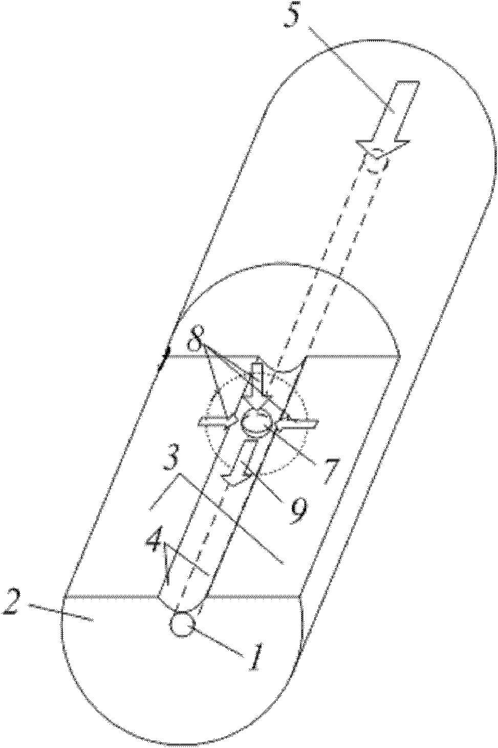
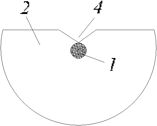
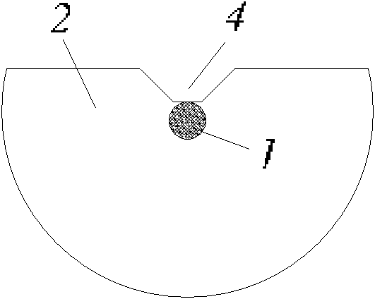
[0038] 1. Polishing and slotting: Take a piece of ordinary single-core optical fiber, and polish and slot one end of the optical fiber to form a figure 1 The side polished slotted fiber shown in the figure should meet the following conditions during the slotting process: (1) the size of the slot can allow tiny particles to pass through smoothly, (2) the distance between the center of the side polished slotted fiber core and the bottom of the slot The distance d satisfies the following relationship: d core / 2≤dclad / 2, in this way, a straight single-core side-polished slotted micro-particle directional drive is completed.
[0039] 2. Particle drive: Immerse the prepared straight single-core side-polished slotted optical fiber micro-particle driver in a solution containing a certain amount of micro-particles 7, and after passing through the laser 5, the micro-particles 7 near the slotted area will be captured And directional movement along the slotting direction, such as figur...
Embodiment 2
[0041] 1. According to the steps in Example 1, a straight single-core side-polished slotted optical fiber micro-particle directional driver is produced;
[0042] 2. Bending the end of the prepared straight single-core side-polished and slotted optical fiber micro-particle directional driver containing the side-polished slot, and then fixing the fiber, such as image 3 , a curved single-core side-polished slotted optical fiber micro-particle directional driver was fabricated;
[0043] 3. Particle drive: Immerse the prepared curved single-core side-polished slotted optical fiber micro-particle driver in a solution containing a certain amount of micro-particles 7, and after the laser 5 is passed through, the micro-particles 7 near the slotted area will be captured and released. Oriented movement along the slotting direction, such as image 3 shown.
Embodiment 3
[0045] 1. Coupling connection: Take a section of multi-core optical fiber whose core is linearly distributed, remove the coating layer and cut one end of the optical fiber, and then perform alignment welding with the single-mode optical fiber 10 with light source pigtail. exist Figure 5 The shown solder joint 11 is heated to a softened state, then tapered, and the optical power is monitored until the optical power coupled to the multi-core optical fiber reaches the maximum;
[0046] 2. Encapsulation protection: adjust the quartz tube with an inner diameter larger than the standard optical fiber or multi-core optical fiber to Figure 6 Shown at the cone coupling zone 12, then at both ends of the quartz tube with CO 2 The laser is heated, welded and sealed, or encapsulated and cured with epoxy resin, and then secondly coated to complete the overall protection;
[0047] 3. Polishing and slotting: side polishing and slotting of one end of the prepared multi-core optical fiber c...
PUM
 Abstract
Description
Claims
Application Information
 - R&D
- Intellectual Property
- Life Sciences
- Materials
- Tech Scout
- Unparalleled Data Quality
- Higher Quality Content
- 60% Fewer Hallucinations
Browse by: Latest US Patents, China's latest patents, Technical Efficacy Thesaurus, Application Domain, Technology Topic, Popular Technical Reports.
© 2025 PatSnap. All rights reserved.Legal|Privacy policy|Modern Slavery Act Transparency Statement|Sitemap|About US| Contact US: help@patsnap.com


