

Embedded cable safety protection assembly box
A safety protection and embedded technology, which is applied in the installation of cables, cable accessories, electrical components, etc., can solve the problems of low efficiency, loading into three-way wiring boxes, and increasing the production cost of manufacturers, so as to avoid waste.
- Summary
- Abstract
- Description
- Claims
- Application Information
AI Technical Summary
Problems solved by technology
Method used
Image

Examples
Embodiment 1
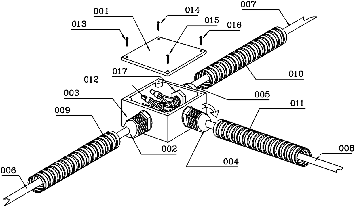
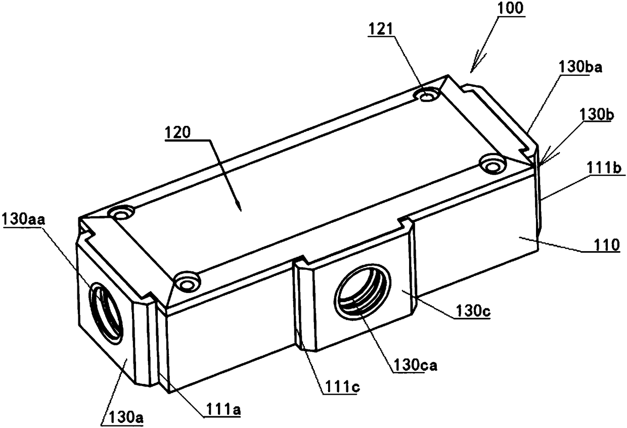
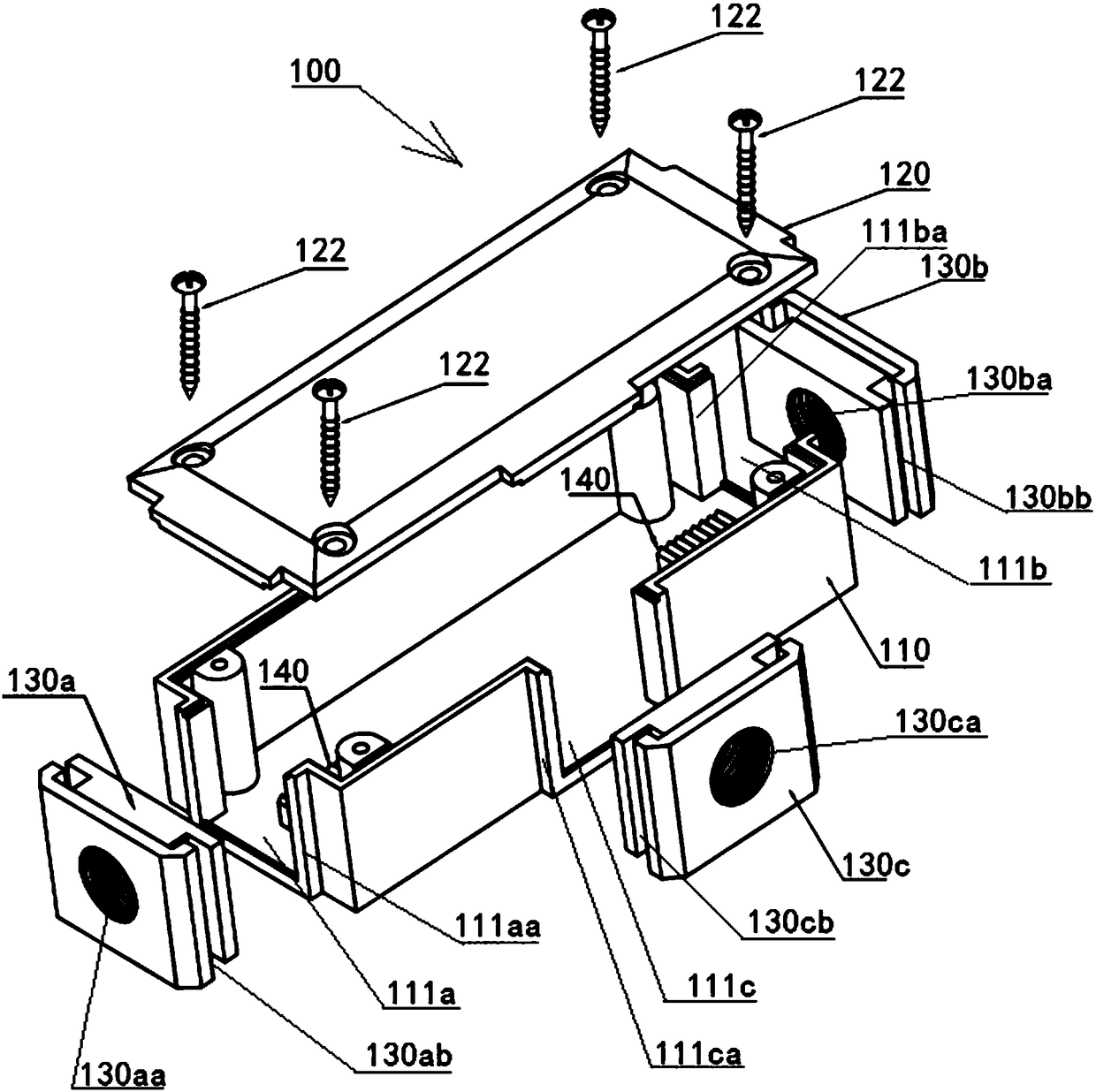
[0026] see figure 2 , 3 As shown in , 7, the embedded cable safety protection assembly box 100 includes an assembly box body 110 and a top cover 120, and the top cover 120 is fixed on the assembly box body 110 by screws 122. The two ends of the assembly box body 110 are provided with main cable inlets 111a and 111b respectively, and the side is provided with branch cable inlets 111c. Inside the assembly box body 100 is provided with at least one limiting component for fixing the main cable. The limiting component in this embodiment is a limiting latch 140 for the cable tie to pass through, and the limiting latch 140 is a Yes, they are respectively arranged at the cable inlets of the main cable inlets 111a and 111b, and the limit latch teeth 140 can further increase the axial tensile force that the cables can bear.
[0027] The main cable inlets 111a, 111b and the branch cable inlets 111c are detachably connected to the screw-on seal heads 130a, 130b, 130c with threaded hole...
Embodiment 2
[0031] see Figure 4 , 5 As shown in , 8 , the embedded cable safety protection assembly box 200 includes an assembly box body 210 and a top cover 220 , and the top cover 220 is fixed on the assembly box body 210 by screws 222 . The two ends of the assembly box body 210 are respectively provided with main cable inlets 211a and 211b, and the side is provided with branch cable inlets 211c. Inside the assembly box body 200 is provided with at least one limiting component for fixing the main cable. The limiting component in this embodiment is a limiting latch 240 for cable ties to pass through. The limiting latch 240 is a Yes, they are respectively arranged at the cable inlets of the main cable inlets 211a and 211b, and the limit latch teeth 240 can further increase the axial tensile force that the cables can bear.
[0032]The main cable inlets 211a, 211b and the branch cable inlets 211c are detachably connected to a pair of half-fitted heads 230a, 230b, 230c respectively, and t...
Embodiment 3
[0036] see Figure 6 As shown, the embedded cable safety protection assembly box 300 includes an assembly box body 310 and a top cover, and the top cover is fixed on the assembly box body 310 by screws. Both ends of the assembly box body 310 are respectively provided with main cable inlets 311a and 311b, and the side is provided with branch cable inlets 311c. Inside the assembly box body 300 is provided with at least one limiting component for fixing the main cable. The limiting component in this embodiment is a limiting latch 340 that can pass through the cable tie 350. The limiting latch 340 is A pair are respectively arranged at the cable inlets of the main cable inlets 311a and 311b, and the limit latch teeth 340 can further increase the axial tensile force that the cables can bear.
[0037] The assembly box body 310 is made of metal material or non-metal material, the metal material is one of stainless steel or iron or aluminum or copper or zinc or lead, and the non-meta...
PUM
 Abstract
Description
Claims
Application Information