Cleaning device for slab mop
A technology of cleaning device and flat mop, which is applied in cleaning carpets, floors, cleaning equipment, etc., and can solve problems such as poor cleaning effect of flat mop
- Summary
- Abstract
- Description
- Claims
- Application Information
AI Technical Summary
Problems solved by technology
Method used
Image
Examples
Embodiment 1
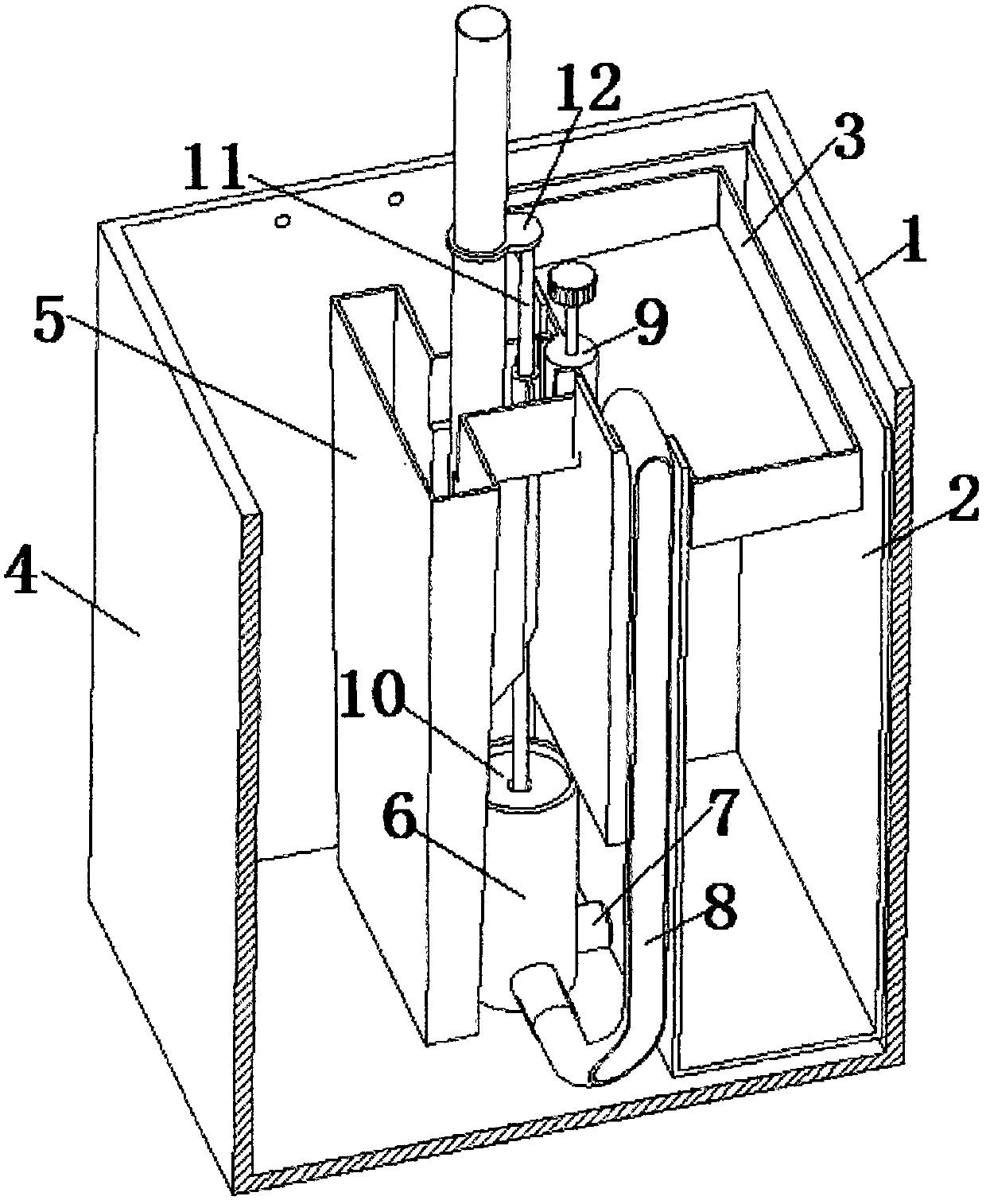
[0052] A flat mop cleaning device, comprising a barrel body 1, a cleaning area, a water purification area 2, a sewage area 4 and a pressurized water chamber 6, the cleaning area communicates with the water purification area 2, and the cleaning area includes The cleaning area body 5 and the water inlet area 3, one end of the pressurized water chamber 6 communicates with the water purification area 2 through the water inlet one-way channel 7, and the other end communicates with the water inlet area 3 through the water outlet one-way channel 8, and the water inlet area 3 The capacity is the same as that of the cleaning area body 5 , and the water inlet area 3 communicates with the cleaning area body 5 through the water inlet area valve 9 .
[0053] The pressure water chamber 6 is provided with a piston 10 and a connecting rod 11 connected to the piston. The flat mop is provided with a stopper 12. When the flat mop is pressed down, the stopper 12 pushes the piston 10 to press down ...
Embodiment 2
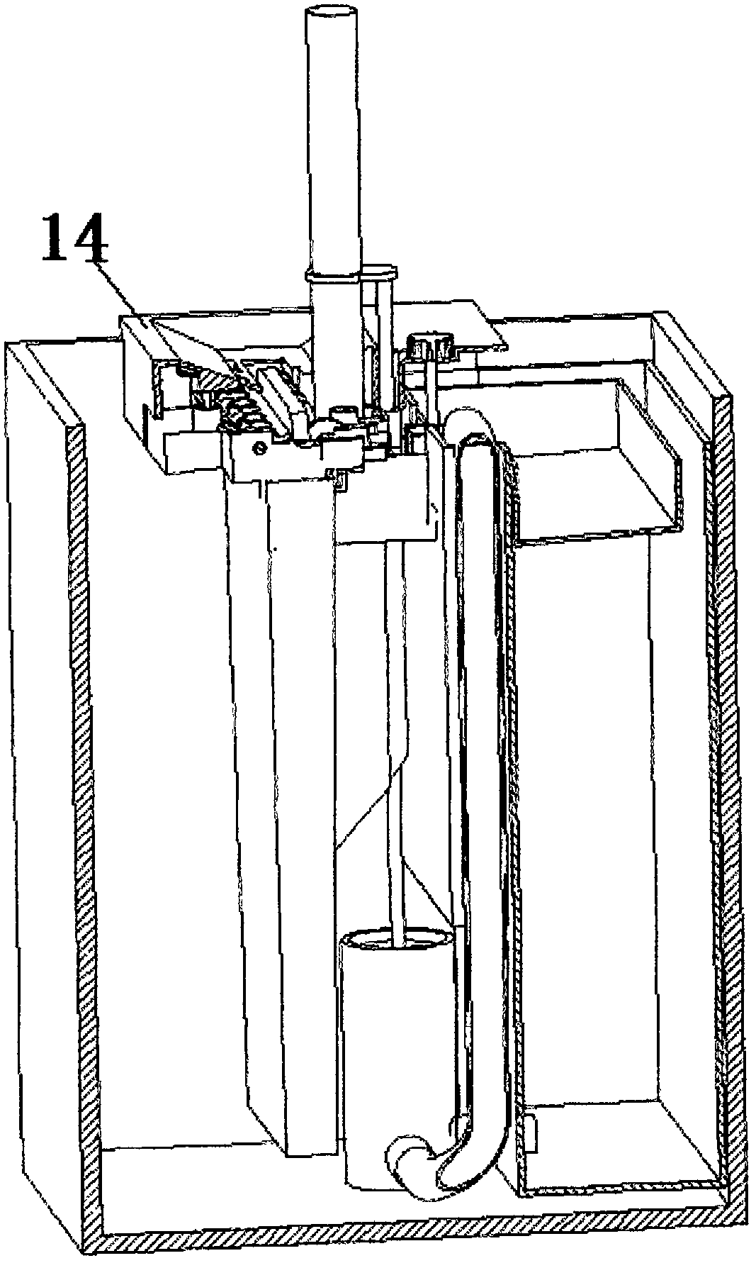
[0056] A flat mop cleaning device described in Embodiment 2 is basically the same as Embodiment 1, including a barrel body 20, a sewage area 24, a water purification area 21, a water inlet area 25, a cleaning area body 27, and a connection between the water inlet area 25 and the water purification area. The pressurized water chamber 23 of the district 21, the bucket body 20 is provided with the water purification district supporting position 22 of supporting the water purification district 21, and this supporting position 22 can be the support base that is positioned at the bottom of the staving body 20 as described in this embodiment or can be provided with The supporting structure supporting the weight of the whole water purification area 21 at the mouth of the barrel body 20 or the inner wall is conventional for those skilled in the art, as long as it can play a supporting role.
[0057] One end of the pressurized water chamber 23 is one-way water inlet channel 26 passing th...
Embodiment 3
[0060] A flat mop cleaning device described in this embodiment is basically the same as Embodiment 1, the difference is that the cleaning device described in this embodiment also includes a control circuit, and the control circuit is provided with a water level sensing end of the water level in the water inlet area and is connected with Inlet valve connection.
[0061] The present invention lists several typical cleaning devices in the embodiment part. In fact, in controlling the water inlet and outlet of the cleaning area, those skilled in the art can selectively use water pumps and / or valves, and the use of control circuits can be extremely Greatly increase the intelligence of the water inlet and outlet of the cleaning area. Of course, as described in Embodiment 1, the use of mechanical methods to control the water inlet and outlet of the washing area can still bring good control effects.
[0062] In addition, the cleaning device of the present invention does not need to be ...
PUM
 Abstract
Description
Claims
Application Information
 - R&D
- Intellectual Property
- Life Sciences
- Materials
- Tech Scout
- Unparalleled Data Quality
- Higher Quality Content
- 60% Fewer Hallucinations
Browse by: Latest US Patents, China's latest patents, Technical Efficacy Thesaurus, Application Domain, Technology Topic, Popular Technical Reports.
© 2025 PatSnap. All rights reserved.Legal|Privacy policy|Modern Slavery Act Transparency Statement|Sitemap|About US| Contact US: help@patsnap.com


