Material conveying mechanism and electric cooker inner container punching equipment

A conveying mechanism and material technology, applied in metal processing equipment, feeding devices, manufacturing tools, etc., can solve problems such as unfavorable production efficiency, and achieve the effect of preventing waste accumulation and speeding up efficiency

Inactive Publication Date: 2018-06-01
DEA GENERAL AVIATION HLDG CO LTD
View PDF6 Cites 0 Cited by
  • Summary
  • Abstract
  • Description
  • Claims
  • Application Information

AI Technical Summary

Problems solved by technology

Picking and placing waste materials into the collection box manually is not conducive to improving production efficiency, and it is easy to cause production safety accidents where employees are injured by waste materials

Method used


Image

  • Material conveying mechanism and electric cooker inner container punching equipment
  • Material conveying mechanism and electric cooker inner container punching equipment

Examples


Embodiment Construction

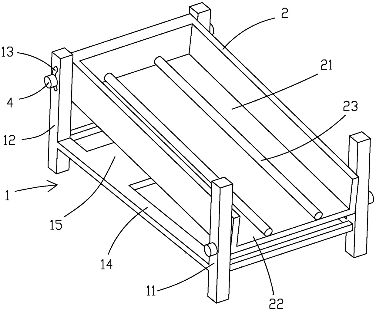
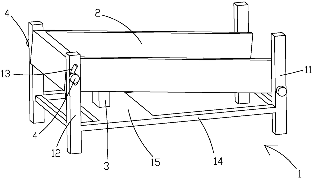
[0021] like figure 1 and figure 2 The material conveying mechanism shown includes a bracket 1 and a feeding seat 2 arranged on the bracket 1, the feeding seat 2 is provided with a feeding chute 21 arranged obliquely, and the lower end of the feeding chute 21 is at the A material outlet 22 is formed on the feeding seat 2, and the end of the feeding seat 2 away from the material outlet 22 is higher than the end of the feeding seat 2 close to the material outlet 22, and the material feeding seat 2 is close to the material outlet 22 One end is hinged on the support 1, the end of the feeding seat 2 away from the material outlet 22 is flexibly connected to the support 1 and can move up and down relative to the support 1, and the material conveying mechanism also includes a The drive device 3 on the support 1 is used to drive the end of the feeding seat 2 away from the material outlet 22 to move up and down relative to the support 1. Specifically, the drive device 3 is a vibrating ...


PUM


Abstract

The invention provides a material conveying mechanism and electric cooker inner container punching equipment. The material conveying mechanism comprises a support and a material conveying seat arranged on the support. An inclined material conveying sliding groove is formed in the material conveying seat. The lower end of the material conveying sliding groove forms a material outlet in the materialconveying seat. The end, near the material outlet, of the material conveying seat is hinged to the support. The end, away from the material outlet, of the material conveying seat is movably connectedwith the support and can move up and down relative to the support. The material conveying mechanism further comprises a driving device arranged on the support and used for driving the end, away fromthe material outlet, of the material conveying seat to move up and down relative to the support. The electric cooker inner container punching equipment comprises the abovementioned material conveyingmechanism. Waste materials fall into the material conveying seat, automatically slide into a collecting frame through the inclined material conveying sliding groove, and do not need to be taken or putmanually. In addition, the driving device is used for driving the material conveying seat to move up and down, thereby preventing the waste materials from accumulating, and further improving the efficiency that the waste materials fall into the collecting frame.

Description

【Technical field】 [0001] The application relates to the technical field of electric rice cooker manufacturing, in particular to a material conveying mechanism and stamping equipment for an inner pot of an electric rice cooker. 【Background technique】 [0002] In the manufacturing process of the inner pot of the electric rice cooker, after the inner pot of the electric rice cooker is stamped and trimmed, the waste generated cannot automatically fall into the corresponding collection frame for waste collection, and it is often necessary to manually pick and place the waste. collection box. Picking and placing waste materials into the collection frame manually is not conducive to improving production efficiency, and it is also easy to cause production safety accidents in which employees are injured by waste materials. 【Content of invention】 [0003] In order to realize the automatic collection of waste materials so as to improve the production efficiency of the inner pot of t...

Claims


Application Information

Patent Timeline
IPC IPC(8): B21D43/02B21D43/20
CPCB21D43/02B21D43/20
Inventor 顾斌阳恩贵欧伟成
Owner DEA GENERAL AVIATION HLDG CO LTD
Why Eureka
Try Eureka