Novel new-energy car device
A new energy vehicle, a new type of technology, applied in the direction of coupling devices, electric vehicles, electric vehicle charging technology, etc., can solve the problems of potential safety hazards, exposure of power connection holes, etc., to increase the safety of use, simple and convenient operation, and increase safety and stability Effect
- Summary
- Abstract
- Description
- Claims
- Application Information
AI Technical Summary
Problems solved by technology
Method used
Image

Examples
Embodiment Construction
[0021] The preferred embodiments of the present invention will be described in detail below in conjunction with the accompanying drawings, so that the advantages and features of the present invention can be more easily understood by those skilled in the art, so as to define the protection scope of the present invention more clearly.
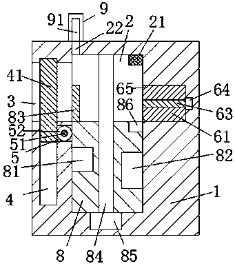
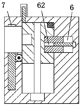
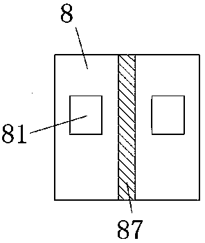
[0022] refer to Figure 1-5 A new type of new energy vehicle device is shown, including a charging pile body 10, a charging part 1 is fixedly installed on the left upper end surface of the charging pile body 10, and a base 11 is fixedly installed on the bottom end surface of the charging pile body 10. Sliding slot 2, the left end surface of the charging part 1 is provided with an inlet hole 3 communicating with the up and down sliding slot 2, the bottom end wall of the inlet hole 3 is provided with an accommodating groove 4, and the top end of the inlet hole 3 The wall is provided with a card slot 7 opposite to the receiving groove 4, and the lef...
PUM
 Abstract
Description
Claims
Application Information
 - Generate Ideas
- Intellectual Property
- Life Sciences
- Materials
- Tech Scout
- Unparalleled Data Quality
- Higher Quality Content
- 60% Fewer Hallucinations
Browse by: Latest US Patents, China's latest patents, Technical Efficacy Thesaurus, Application Domain, Technology Topic, Popular Technical Reports.
© 2025 PatSnap. All rights reserved.Legal|Privacy policy|Modern Slavery Act Transparency Statement|Sitemap|About US| Contact US: help@patsnap.com