
Load reducing and high lift device applied to unmanned aerial vehicle

A high-lift device and unmanned aerial vehicle technology, applied in the field of unmanned aerial vehicles, can solve problems such as crashes, complex mechanical conversion accuracy, difficulty in flight control control, and difficulty in ensuring no failure rate, etc., to achieve flight speed slowing down, wing load light effect

Pending Publication Date: 2018-06-01
GUANGZHOU GUANGHONG AEROSPACE TECH CO LTD
View PDF0 Cites 0 Cited by
  • Summary
  • Abstract
  • Description
  • Claims
  • Application Information

AI Technical Summary

Problems solved by technology

[0006] 4. A fixed-wing aircraft with a conventional layout needs to roll until the lift is equal to or greater than the speed of gravity before it can take off and climb. When landing, open the flaps and slide down. It cannot fly and touch down at a speed lower than the set critical stall speed.
However, this tilting system is very complicated, which puts forward high requirements on the precision of mechanical conversion and the difficulty of flight control control. It is difficult to guarantee the failure rate. Once the mechanism fails, it will cause the risk of crashing, and it will increase the difficulty of daily maintenance and maintenance.

Method used


Image

  • Load reducing and high lift device applied to unmanned aerial vehicle
  • Load reducing and high lift device applied to unmanned aerial vehicle
  • Load reducing and high lift device applied to unmanned aerial vehicle

Examples


Embodiment 1

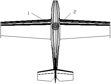
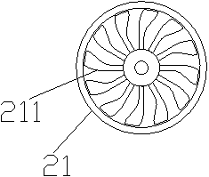
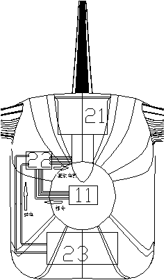
[0033] see Figure 1-4 , a load reduction and lifting device applied to unmanned aerial vehicles, including: an electric ducted fan 21, an electronic speed controller 22 and a power supply unit 23; the electric ducted fan 21 is installed near the center of the unmanned aerial vehicle 1; The drone 1 is provided with a flight controller 11; the flight controller 11, the electronic governor 22 and the electric ducted fan 21 are connected in sequence, and the electronic governor 22 is connected to the power supply unit 23; During the take-off or landing process of the aircraft 1, the flight controller 11 controls the electronic governor 22 to output power to the electric ducted fan 21, and the electric ducted fan 21 rotates according to the power to generate lift.

[0034] The flight controller 11 outputs instructions to the electronic governor 22, and the electronic governor 22 inputs power to the motor according to the instructions, and the motor drives the electric ducted fan t...

Embodiment 2

[0048] see Figure 5-6 , The difference between this embodiment and Embodiment 1 is that it includes: a left load reducing and increasing device 31 and a right reducing and increasing device 32, and the left reducing and increasing device 31 includes a left electric ducted fan 311, a left electronic adjustable speed device 312 and power supply unit 33, the right load reduction device 32 includes a right electric ducted fan 321, a right electronic governor 322 and a power supply unit 33; the left electric ducted fan 311, left electronic governor 312 is connected to the flight controller 11; the right electric ducted fan 321, the right electronic governor 322 are connected to the flight controller 11; the power supply unit 33 and the left electronic governor 312 and the right electronic governor 322 are all Connection; the left load-reducing and increasing-lifting device 31 is installed on the left wing close to the fuselage, the right reducing-load increasing-lifting device 32 ...


PUM


Abstract

The invention relates to a load reducing and high lift device applied to an unmanned aerial vehicle. The device includes: an electric ducted fan, an electronic speed controller and a power supply unit, wherein the electric ducted fan is installed nearby the gravity center of the unmanned aerial vehicle. A flight controller is arranged on the unmanned aerial vehicle. The flight controller, the electronic speed controller and the electric ducted fan are successively connected. The electronic speed controller is connected to the power supply unit. During takeoff and landing of the unmanned aerialvehicle, the flight controller controls the electronic speed controller to output power quantity to the electric ducted fan; then the electric ducted fan generates lifting force according to the power quantity. During the takeoff and landing of the unmanned aerial vehicle, the flight controller controls the electronic speed controller to output power quantity to the electric ducted fan; then theelectric ducted fan generates lifting force according to the power quantity, so that a part of self weight of the UAV is reduced and wing load is reduced; as a result, flight speed can be reduced thanthat in regular flight, thus achieving low-speed short-distance safe takeoff and landing.

Description

technical field [0001] The invention relates to the technical field of unmanned aerial vehicles, in particular to a load-reducing and lifting-increasing device applied to unmanned aerial vehicles. Background technique [0002] As we all know, the current fixed-wing unmanned aircraft with conventional layout needs a long runway to support take-off and landing. Only a longer runway can accumulate enough take-off speed to meet the initial speed of take-off; landing also requires a larger glide speed and a longer ground taxiing length. Without long runways, fixed-wing aircraft cannot take off and land. In response to this problem, there are currently several solutions in the field of drones: [0003] 1. Fixed-wing vertical take-off and landing technology, such as XFV-1, is the simplest and rude design of a fixed-wing that can be erected, straight up and down without stunts. [0004] 2. Vertical take-off and landing fixed-wing technology, use the four-rotor mode (four propelle...

Claims


Application Information

Patent Timeline
Patent Type & Authority Applications(China)
IPC IPC(8): B64C39/02
CPCB64C39/02B64U30/10B64U10/25B64U50/19B64U30/20B64U50/14
Inventor 黄永明黎广宇梁生智
Owner GUANGZHOU GUANGHONG AEROSPACE TECH CO LTD
Learn More