
A balance wheel sorting device
A sorting device and swing arm technology, applied in the direction of transportation and packaging, conveyor objects, etc., can solve the problems of inconvenient logistics item sorting, single use performance, complex structure, etc., to achieve reasonable design, simple operation, and improved classification. The effect of picking efficiency
- Summary
- Abstract
- Description
- Claims
- Application Information
AI Technical Summary
Problems solved by technology
Method used
Image

Examples
Embodiment
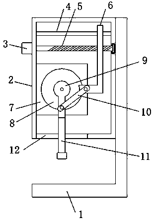
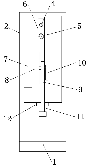
[0016] refer to Figure 1-2 , a balance wheel sorting device, including a fixed frame 1 and a device body 2, the device body 2 is a cavity structure, the device body 2 is fixedly installed on the top side of the fixed frame 1, and the side of the device body 2 away from the fixed frame 1 A motor 3 is fixedly installed on the outer wall, and a support rod 4 and a threaded rod 5 arranged horizontally are respectively connected between the inner walls on both sides of the device body 2, wherein the support rod 4 is located above the threaded rod 5, and between the support rod 4 and the threaded rod 5 There is a vertical movable plate 6 connected between them, the support rod 4 is slidingly connected with the movable plate 6, the threaded rod 5 is vertically connected with the threaded movable plate 6, one end of the threaded rod 5 is connected with the output shaft of the motor 3, and the device body 2 is close to the motor A fixed plate 7 vertically arranged on the inner wall of...
PUM
 Abstract
Description
Claims
Application Information