
Multifunctional lock body

A multi-functional lock body technology, which is applied in building locks, electric alarm locks, locks controlled by non-mechanical transmission, etc., can solve problems such as single function point or structure point feature

Inactive Publication Date: 2018-06-01
安立圣(杭州)科技有限公司
View PDF0 Cites 14 Cited by
  • Summary
  • Abstract
  • Description
  • Claims
  • Application Information

AI Technical Summary

Problems solved by technology

However, among the existing lock bodies currently on the market, their functional points or structural features are relatively single, and there is a lack of a lock body with a complete combination of functional structures.

Method used


Image

  • Multifunctional lock body
  • Multifunctional lock body

Examples


Embodiment Construction

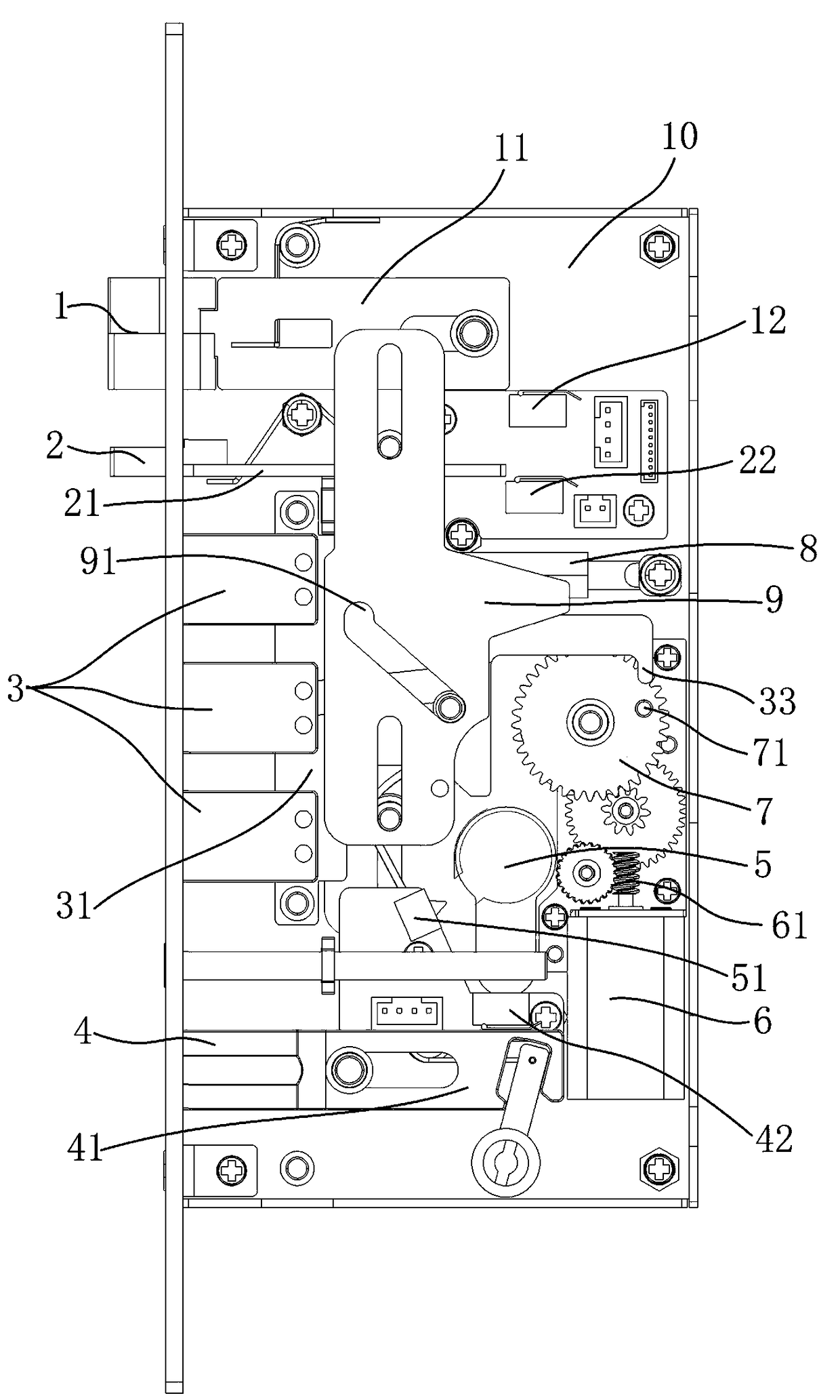
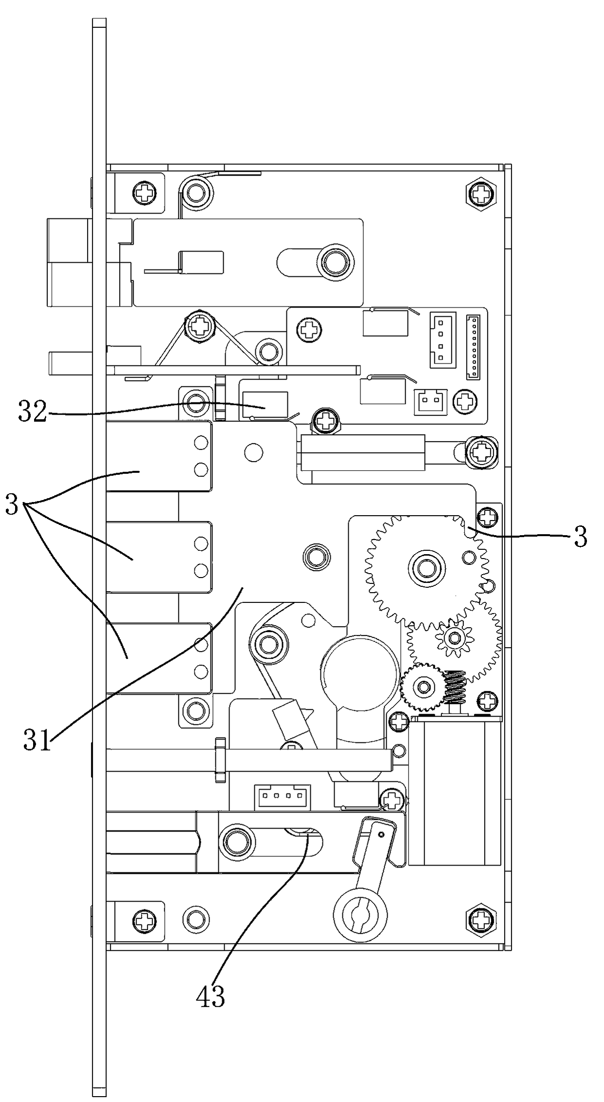
[0013] Such as Figures 1 to 2 As shown, a multifunctional lock body of the present invention includes a lock body lower cover 10, a small bolt 2, a main bolt 3, an anti-bolt 4, and corresponding small bolt picks 21, main bolt picks 31 , anti-bolt paddle 41, the multifunctional lock body is provided with a drive system made up of motors and gears, and some sensors for monitoring each deadbolt paddle, and the lock body is also provided with a two-way tongue 1 and a two-way tongue 1 connected to each other Two-way tongue pick 11, and several sensors for monitoring each deadbolt pick, including two-way tongue pick sensor 12, small deadbolt pick sensor 22, main deadbolt pick sensor 32, reverse deadbolt pick sensor 42 , respectively used to monitor the position and motion of each deadbolt. A paddle sensor 51 is provided next to the keyhole 5 inside the lock body lower cover 10. When the key is inserted into the keyhole 5 and rotated, the paddle sensor 51 will be triggered. The low...


PUM


Abstract

A multifunctional lock body includes a lock body upper cover, a lock body lower cover, a two-way tongue, a small lock tongue and a main lock tongue, and a corresponding two-way tongue poking piece, small lock tongue poking piece and main lock tongue poking piece. The multifunctional lock body is characterized in that the interior of the multifunctional lock body is provided with a drive system which is composed of a motor and gears and a plurality of sensors for monitoring the lock tongue poking pieces.

Description

technical field [0001] The invention relates to a door panel lock body, in particular to a multifunctional lock body. Background technique [0002] There are various styles of lock bodies on the market, but the core parts of the lock bodies are actually similar. Some lock bodies are locked by motor drive, while others are locked by mechanical drive. Further, some lock bodies are equipped with a deceleration device to improve its quiet effect, while some lock bodies are equipped with some sensors to improve its controllability. However, in the existing lock bodies currently on the market, their functional points or structural features are relatively single, and there is a lack of a lock body with a complete combination of functional structures. Contents of the invention [0003] The purpose of the present invention is to provide a multifunctional lock body with complete structure and functions, which is dedicated to perfecting the user's functional requirements for the loc...

Claims


Application Information

Patent Timeline
IPC IPC(8): E05B47/00E05B15/00E05B63/14E05B45/06
CPCE05B47/0012E05B15/00E05B45/06E05B63/146E05B2045/0635E05B2045/065E05B2047/002E05B2047/0069
Inventor 颜燕娟郑成富
Owner 安立圣(杭州)科技有限公司
Learn More