
A mining hydraulic rock splitter

A rock-cracking and hydraulic technology, applied in the direction of discharge machinery, earth square drilling and mining, etc., can solve the problems of environmental workers' damage, ore size splitting, ore splitting inconvenient, etc., and achieve the effect of convenient connection and insertion

Active Publication Date: 2019-11-05
山东能源集团鲁西矿业有限公司 +1
View PDF2 Cites 1 Cited by
  • Summary
  • Abstract
  • Description
  • Claims
  • Application Information

AI Technical Summary

Problems solved by technology

[0003] Coal mines are the main source of energy in our country, but sometimes large ores need to be split when mining coal mines. The traditional method is generally to use detonators and explosives for blasting, but the use of detonators will cause damage and harm to the environment and staff, but The size of the ore is different, and many times it cannot be split well, and the ore is rough and the mechanical equipment is not easy to enter, so the splitting of the ore is even more inconvenient.

Method used


Image

  • A mining hydraulic rock splitter
  • A mining hydraulic rock splitter
  • A mining hydraulic rock splitter

Examples


Embodiment 1

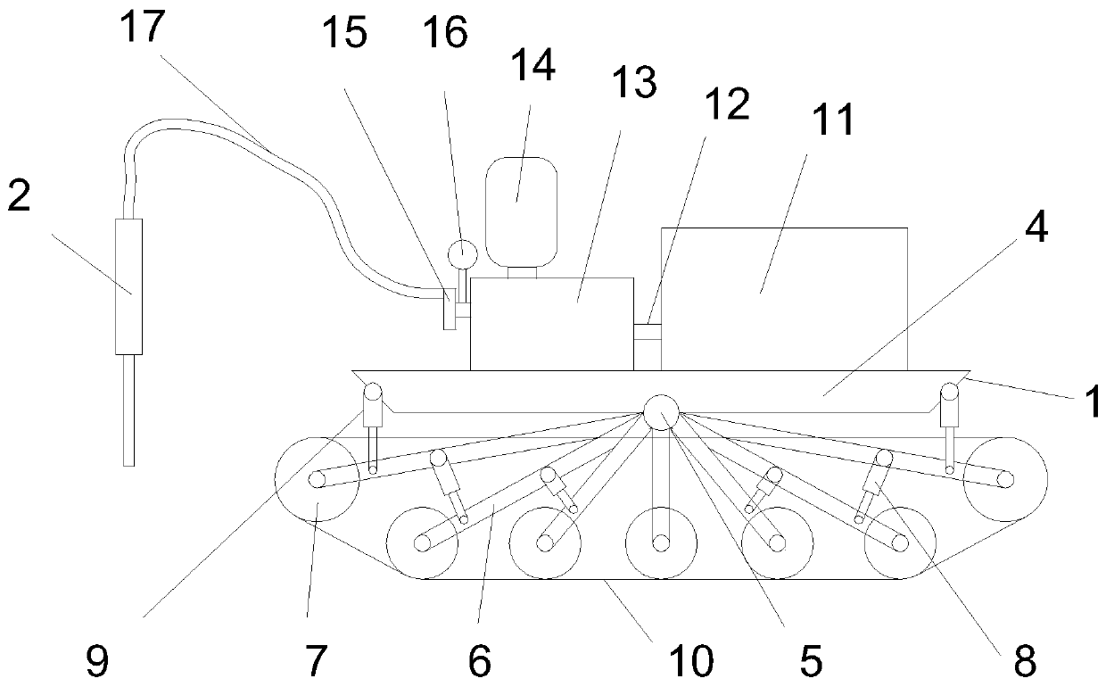
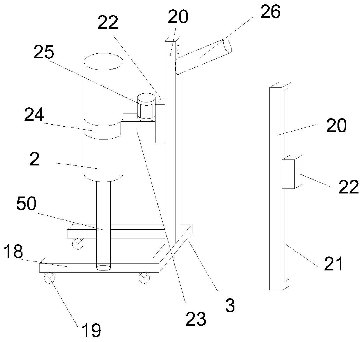
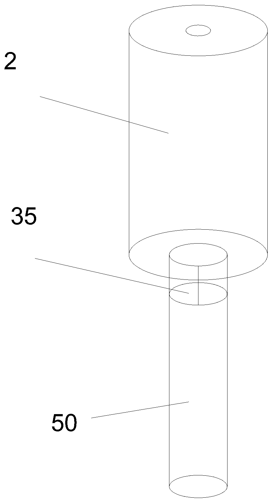
[0021] Embodiment 1: A hydraulic rock cracking machine for mining, comprising a moving device 1, a rock cracker 2 and a rock cracking support device 3. The moving device 1 is provided with a chassis 4, and the bottom of the chassis 4 is provided with a connecting shaft 5. A connecting wheel rod 6 is connected to the connecting shaft 5, one end of the connecting wheel rod 6 is provided with a crawler wheel 7, a hydraulic rod 8 is provided between the connecting wheel rods 6, and both sides of the chassis 4 are provided Damping hydraulic rod 9, said damping hydraulic rod 9 is connected with connecting wheel rods 6 on both sides. The crawler wheel 7 is provided with crawlers 10, and the connecting wheel rod 6 can be damped by rotating the connecting shaft 5, and the connecting wheel rod 6 The hydraulic rod 8 in between can better dampen the mobile device and facilitate the movement of the device.

[0022] The upper side of the chassis 4 is provided with a hydraulic oil tank 11, the ...


PUM


Abstract

The invention discloses a hydraulic rock splicing machine for a mine. The hydraulic rock splicing machine comprises a moving device, a rock splicing device and a rock splicing supporting device. The moving device is provided with a chassis. The lower side of the chassis is provided with a connecting shaft. The connecting shaft is connected with connecting wheel rods. One end of each connecting wheel rod is provided with a crawler wheel. A hydraulic rod is arranged between the connecting wheel rods. The two sides of the chassis are provided with damping hydraulic rods. The damping hydraulic rods are connected with the connecting wheel rods on the two sides. The crawler wheels are provided with caterpillar bands. According to the hydraulic rock splicing machine for the mine, a rock splicingdevice which is more efficient and more practical is provided, the hydraulic rock splicing machine is easier during ore splicing and can move better on a rugged mountain or in the mine, splicing rodscan further be connected according to the splicing depth required by splicing of ore, and moving of the rock splicing device and connecting and inserting of the splicing rods are further be facilitated.

Description

Technical field [0001] The invention discloses a mining hydraulic rock cracking machine, in particular to a mining hydraulic rock cracking machine. [0002] technical background [0003] Coal mines are the main source of energy in our country, but the mining of coal mines sometimes needs to split large ores. The traditional method is generally to use detonator explosives for blasting, but the use of detonators will cause damage and harm to the environment and staff. Ores of different sizes cannot be split well in many cases, and the ores are in rugged and uneven places and mechanical equipment is not easy to enter, so the splitting of ores is even more inconvenient. Summary of the invention [0004] The purpose of the present invention is to provide a hydraulic rock cracking machine for mining, which has solved the problems raised in the background art. The equipment will be easier to split ore, and it can move better in rugged mountains or mines. The splitting rod can also be conn...

Claims


Application Information

Patent Timeline
Patent Type & Authority Patents(China)
IPC IPC(8): E21C37/26
CPCE21C37/26
Inventor 张涛吴高镇田胜利石刚董勤凯李常友邵珠娟
Owner 山东能源集团鲁西矿业有限公司
Learn More