Eureka AIR delivers breakthrough ideas for toughest innovation challenges, trusted by R&D personnel around the world.

Monitoring device for environment control based on hydraulic power generation technique

A technology for environmental governance and monitoring device, applied in the field of environmental governance, can solve the problems such as the inability to control the monitoring depth of the monitoring device and the inability of the monitoring device to work stably for a long time, and achieve the effects of simple structure, convenient operation and increased service life.

Inactive Publication Date: 2018-06-01
郑州东之诺科技有限公司
View PDF12 Cites 3 Cited by
  • Summary
  • Abstract
  • Description
  • Claims
  • Application Information

AI Technical Summary

Problems solved by technology

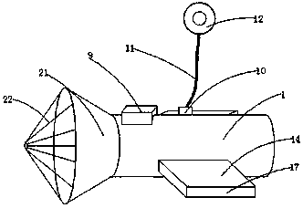
[0004] The purpose of the present invention is to solve the problem that the monitoring device in the prior art cannot work stably for a long time, and cannot control the monitoring depth of the monitoring device, and proposes a monitoring device for environmental governance based on hydropower technology

Method used


Image

  • Monitoring device for environment control based on hydraulic power generation technique
  • Monitoring device for environment control based on hydraulic power generation technique
  • Monitoring device for environment control based on hydraulic power generation technique

Examples


Embodiment Construction

[0023] The technical solutions in the embodiments of the present invention will be clearly and completely described below in conjunction with the accompanying drawings in the embodiments of the present invention. Obviously, the described embodiments are only some of the embodiments of the present invention, not all of them.

[0024] In describing the present invention, it should be understood that the terms "upper", "lower", "front", "rear", "left", "right", "top", "bottom", "inner", " The orientation or positional relationship indicated by "outside", etc. is based on the orientation or positional relationship shown in the drawings, and is only for the convenience of describing the present invention and simplifying the description, rather than indicating or implying that the referred device or element must have a specific orientation, so as to Specific orientation configurations and operations, therefore, are not to be construed as limitations on the invention.

[0025] refer ...


PUM


Abstract

The invention discloses a monitoring device for environment control based on a hydraulic power generation technique. The monitoring device comprises a first monitoring cylinder and a second monitoringcylinder, wherein the first monitoring cylinder and the second monitoring cylinder are respectively of a structure of which both ends are not sealed; the second monitoring cylinder is sheathed by thefirst monitoring cylinder; the two ends of the first monitoring cylinder are sealed with the two ends of the second monitoring cylinder; the inside wall of the first monitoring cylinder is fixedly connected with a miniature hydraulic power generator, a storage battery and a resistor, and the storage battery and the resistor are arranged at one side of the miniature hydraulic power generator; a rotary hole is formed in the part, corresponding to the miniature hydraulic power generator, of the side wall of the second monitoring cylinder, the input end of the miniature hydraulic power generatoris connected with a rotary shaft through a coupling, and one end, away from the miniature hydraulic power generator, of the rotary shaft penetrates through the rotary hole, extends up to be connectedwith an impeller. The monitoring device has the advantages that the structure is simple, the operation is convenient, and the service life of a steel wire rope is greatly prolonged; by arranging the miniature hydraulic power generator, the monitoring device can stably work for a long time in the field; the monitoring depth can be changed according to use requirements.

Description

technical field [0001] The present invention relates to the technical field of environmental treatment, in particular to a monitoring device for environmental treatment based on hydropower technology. Background technique [0002] The ecological environment is closely related to human beings and has an important impact on human life and production activities. The destruction of the ecological environment also has a huge adverse impact on human life and production activities. Human beings digitize many factors through various instruments , and then formulate a specific approach to governance. [0003] People cannot live without water. As the pollution of water resources has become more and more serious in recent years, environmental protection departments have paid more and more attention to the monitoring of water areas. Randomly controlling the depth of the monitoring device to monitor the waters cannot accurately collect the required monitoring data. invention content ...

Claims


Application Information

Patent Timeline
IPC IPC(8): G01N33/18F03B13/00
CPCF03B13/00G01N33/18
Inventor 张晓静
Owner 郑州东之诺科技有限公司
Why Eureka
Eureka Blog
Learn More