A power battery box cooling structure and its control method

A technology for cooling structures and power batteries, applied in battery temperature control, batteries, structural parts, etc., can solve problems such as low cooling efficiency and deformation of rigid pipeline structures, and achieve improved cooling efficiency, increased bonding area, and simple logic. Effect

Active Publication Date: 2020-08-11
HARBIN UNIV OF SCI & TECH
View PDF10 Cites 0 Cited by
  • Summary
  • Abstract
  • Description
  • Claims
  • Application Information

AI Technical Summary

Problems solved by technology

[0004] The purpose of the present invention is to solve the problems of structural deformation and low cooling efficiency of existing rigid pipelines after long-term operation, thereby providing a power battery box cooling structure and its control method

Method used


Image

  • A power battery box cooling structure and its control method
  • A power battery box cooling structure and its control method
  • A power battery box cooling structure and its control method

Examples


specific Embodiment approach 1

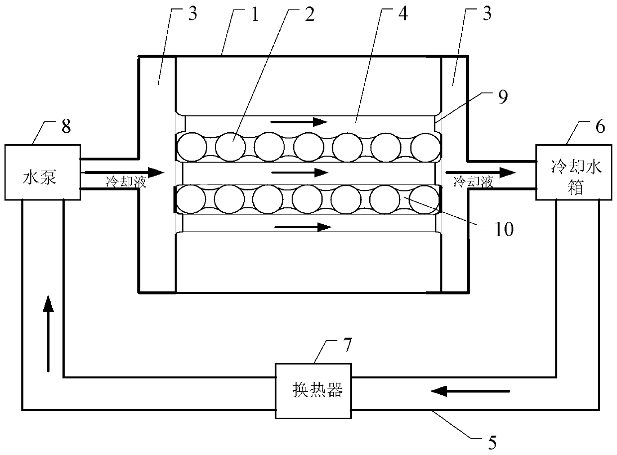
[0032] Specific implementation mode one: combine figure 1 Describe this embodiment in detail, the

[0033] A power battery box cooling structure for cooling the battery module 2 inside the battery box body 1, including two small water storage tanks 3, a flexible water jacket 4, a cooling water tank 6, a heat exchanger 7 and a water pump 8;

[0034] A small water storage tank 3 is respectively provided at both ends of the battery box body 1, and a plurality of battery modules 2 are arranged between the two small water storage tanks 3, and the battery module 2 is formed by a plurality of battery arrays, adjacent to each other. A flexible water jacket 4 is provided between the battery modules 2, one end of the flexible water jacket 4 is used as a water inlet to communicate with a small water storage tank 3, and the other end of the flexible water jacket 4 is used as a water outlet to communicate with another small water storage tank 3 , outside the battery box body 1, two small ...

specific Embodiment approach 2

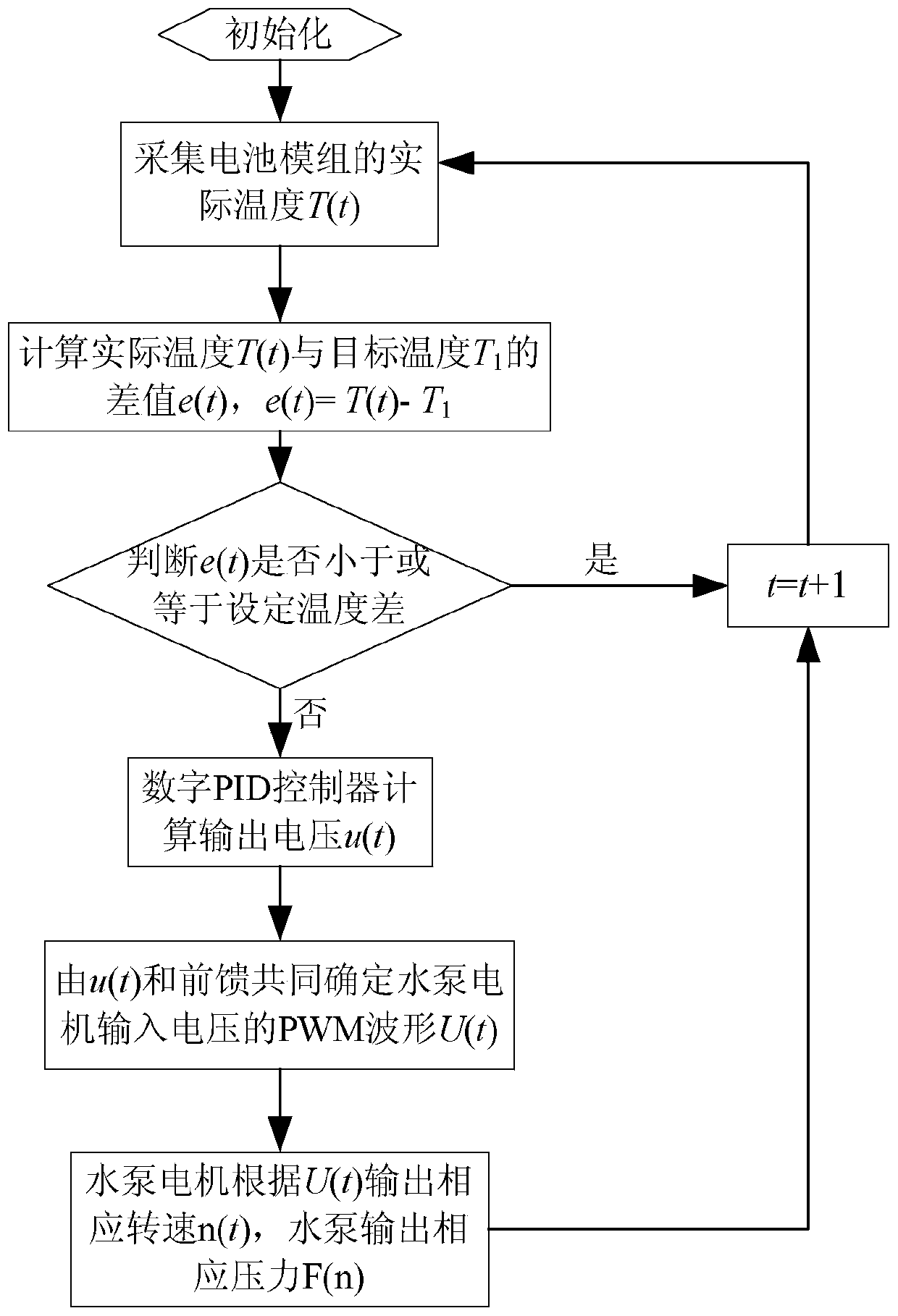
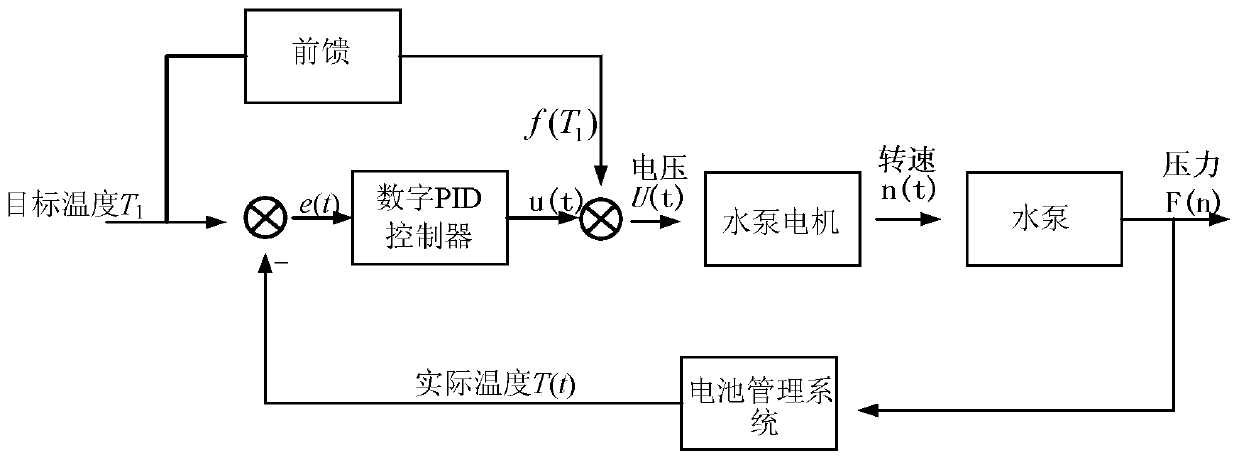
[0040] Specific implementation mode two: combination figure 2 with image 3 Specifically explain this embodiment, a method for controlling the cooling structure of a power battery box described in this embodiment, the method is to use the digital PID controller to receive the collected actual temperature of the battery module 2 to control the output speed of the water pump 8 and pressure, including the following steps:

[0041] Step 1, initialization, let t=2, u(1), e(1) and e(0) are all 0;

[0042] u(t), e(t) are the difference between the output voltage of the digital PID controller, the actual temperature and the target temperature;

[0043] Step 2, the battery management system collects the actual temperature T(t) of the battery module 2;

[0044] Step 3. Calculate the actual temperature T(t) and the target temperature T 1 The difference e(t), e(t)=T(t)-T 1 ;

[0045] Step 4. Determine whether e(t) is less than or equal to the set temperature difference T μ , if th...


PUM


Abstract

A power battery box cooling structure and a control method thereof relate to the battery box cooling technology, in order to solve the problems of structural deformation and low cooling efficiency that may occur after the existing rigid pipeline runs for a long time. The structure is that a flexible water jacket is provided between adjacent battery modules, and an external water channel is used to communicate between the outside of the battery box and the two small water storage tanks to form a circulating water channel, which is sequentially arranged on the external water channel along the direction of water flow. Cooling tanks, heat exchangers and pumps. This method is to collect the actual temperature T(t) of the battery module, calculate T(t) and the target temperature T 1 The difference e(t), the digital PID controller calculates the output voltage u(t), determines the PWM waveform U(t) of the input voltage of the water pump motor, the water pump motor outputs the corresponding speed n(t) according to U(t), and the water pump output The corresponding pressure F(n). The invention is suitable for cooling batteries.

Description

technical field [0001] The invention relates to battery box cooling technology. Background technique [0002] Due to space constraints, the battery pack is arranged relatively compactly inside the electric vehicle, and the temperature is likely to be too high. If there are no reasonable cooling measures, the temperature of the battery pack will rise, the charge and discharge performance of the battery pack will decrease, and the battery will be overcharged and overdischarged, resulting in shortened battery life. The main cooling methods currently used are air cooling, liquid cooling, and phase change material cooling. Liquid cooling has become the preferred solution for many electric vehicles because of its good cooling effect. [0003] Patent applications 201510591143.9 and 201710301415.6 are aimed at cooling water jackets for cylindrical batteries. The water jackets are set in the shape of a flat tube and arranged around the battery in a wave shape. The wavy arc part fit...

Claims


Application Information

Patent Timeline
Patent Type & Authority Patents(China)
IPC IPC(8): H01M10/613H01M10/625H01M10/63H01M10/633H01M10/653H01M10/6556H01M10/6568H01M2/10H01M50/249
CPCH01M10/613H01M10/625H01M10/63H01M10/633H01M10/653H01M10/6556H01M10/6568H01M2220/20H01M50/20Y02E60/10
Inventor 吴晓刚王文博
Owner HARBIN UNIV OF SCI & TECH
Why Eureka
Try Eureka