Signal configuration, sending method and device
A technology for signal configuration and pilot frequency configuration, applied in the field of communication, can solve the problem of large overhead of transmission waveform indication information, and achieve the effect of solving the excessive overhead of transmission waveform indication information and improving resource utilization.
- Summary
- Abstract
- Description
- Claims
- Application Information
AI Technical Summary
Problems solved by technology
Method used
Image
Examples
Embodiment 1
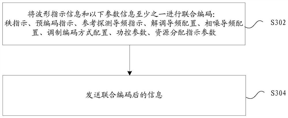
[0034] In this embodiment, a signal configuration method is provided, 图3. Is a flowchart of a signal configuration method according to an embodiment of the present disclosure, such as 图3. As shown in, the process includes the following steps:
[0035] Step S302: jointly encode the waveform indication information and at least one of the following parameter information: rank indication (RI), precoding indication PMI, reference detection pilot indication SRI, demodulation reference signal (DMRs) configuration, phase tracking reference signal (phase tracking reference signal) configuration, modulation coding scheme (MCS) configuration, power control parameters and resource allocation indication parameters;
[0036] After sending the encoded information in step S304.
[0037] Through the above steps, through the joint coding of waveform indication information and other parameter information, the technical problem of excessive overhead of transmitting waveform indication information in ...
Embodiment 2
[0067] In this embodiment, a signal configuration and indication device is also provided. The device is used to realize the above embodiment and preferred embodiment. It will not be repeated if it has been described. As used below, the term "module" may be a combination of software and / or hardware that implements a predetermined function. Although the devices described in the following embodiments are preferably implemented in software, the implementation of hardware, or a combination of software and hardware, is also possible and envisaged.
[0068] 图6. Is a structural block diagram of a signal configuration device according to an embodiment of the present disclosure, such as 图6. As shown, the device comprises:
[0069] An encoding module 60 for jointly encoding the waveform indication information and at least one of the following parameter information: rank indication, precoding indication, reference detection pilot indication, demodulation pilot configuration, phase-to-noise...
Embodiment 3
[0082] This embodiment is an optional embodiment according to the present disclosure, which is used to describe the application in detail in combination with specific embodiments:
[0083] In the joint coding technology of this embodiment, the dynamic switching of waveform indication (WI) mainly uses the following characteristics to reduce the overhead:
[0084] Different sets of optional waveform types can be considered for different codewords. For example, some codewords will destroy the PAPR. Even if dft-s-ofdm is used, the PAPR cannot be controlled, so it will not be combined with it
[0085] The set of optional waveform types supported can be considered for different rank / layer values.
[0086] Different sets of optional waveform types can be considered for different resource regions. Using the same waveform will improve the performance of uplink MU-MIMO (multiple user multiple input multiple output), so you can divide the resource area and set the corresponding waveform ty...
PUM
 Abstract
Description
Claims
Application Information
 - R&D
- Intellectual Property
- Life Sciences
- Materials
- Tech Scout
- Unparalleled Data Quality
- Higher Quality Content
- 60% Fewer Hallucinations
Browse by: Latest US Patents, China's latest patents, Technical Efficacy Thesaurus, Application Domain, Technology Topic, Popular Technical Reports.
© 2025 PatSnap. All rights reserved.Legal|Privacy policy|Modern Slavery Act Transparency Statement|Sitemap|About US| Contact US: help@patsnap.com


