Channel selection method and device

A channel and channel numbering technology, which is applied in the field of channel selection methods and devices, and can solve problems such as large downlink signaling overhead

Active Publication Date: 2019-08-27
BAICELLS TECH CO LTD
View PDF4 Cites 0 Cited by
  • Summary
  • Abstract
  • Description
  • Claims
  • Application Information

AI Technical Summary

Problems solved by technology

[0006] Embodiments of the present invention provide a channel selection method and device to at least solve the problem of excessive downlink signaling overhead caused by uplink scheduling grants in the prior art when a large number of users transmit data in the enhanced physical uplink control channel question

Method used


Image

  • Channel selection method and device
  • Channel selection method and device
  • Channel selection method and device

Examples


Embodiment 1

[0049] According to an embodiment of the present invention, an embodiment of a channel selection method is provided. It should be noted that the steps shown in the flowcharts of the accompanying drawings can be executed in a computer system such as a set of computer-executable instructions, and, although in The flowcharts show a logical order, but in some cases the steps shown or described may be performed in an order different from that shown or described herein.

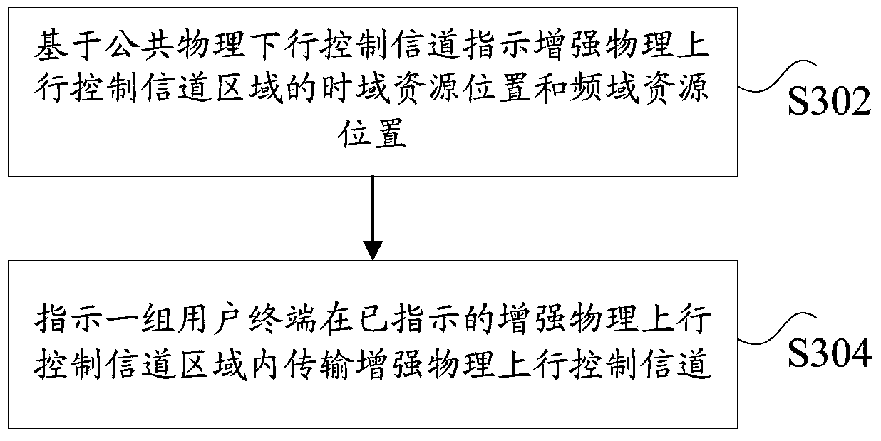
[0050] image 3 is a flowchart of a channel selection method according to an embodiment of the present invention, such as image 3 As shown, the method includes the following steps:

[0051] Step S302, based on the Common Physical Downlink Control Channel (Common PDCCH, C-PDCCH for short), indicating the time domain resource position and the frequency domain resource position of the Enhanced Physical Uplink Control Channel region;

[0052] Step S304, instruct a group of user terminals to transmit the enhanced phy...

Embodiment 2

[0092] In the channel selection method provided in the embodiment of the present invention, the enhanced physical uplink control channel (ePUCCH) time domain resource location and frequency domain resource location are indicated through the common physical downlink control channel (C-PDCCH), specifically:

[0093] Step S1, indicating the time domain position of the enhanced physical uplink control channel region.

[0094] Specifically, it includes: the Nth subframe after the subframe that sends the common physical downlink control channel is the subframe where the enhanced physical uplink control channel area is located, where N is RRC configuration or pre-specified; or according to the information carried on the public physical downlink control channel The Nth subframe after the current subframe indicated by the downlink control information DCI is the subframe where the enhanced physical uplink control channel region is located.

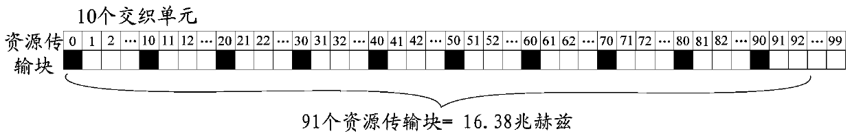
[0095] Step S2, indicating the frequency doma...


PUM


Abstract

The invention discloses a channel selection method and device. Wherein, the method includes: indicating the time domain resource position and the frequency domain resource position of the enhanced physical uplink control channel region based on the common physical downlink control channel; instructing a group of user terminals to transmit the enhanced physical uplink control channel region in the indicated enhanced physical uplink control channel region A control channel, wherein different user terminals transmit the enhanced physical uplink control channel in different indicated enhanced physical uplink control channel regions. The invention solves the technical problem of excessive downlink signaling overhead caused by uplink scheduling authorization in the prior art when a large number of users transmit data in the enhanced physical uplink control channel.

Description

technical field [0001] The present invention relates to the communication field, in particular to a channel selection method and device. Background technique [0002] The existing mobile communication system refers to that operators deploy wireless access network equipment (such as base stations, evolvedNode B, eNB for short) and core network equipment (such as home location registers, Home Location Register, HLR for short) and other equipment to serve as user terminals. (such as a mobile phone) A system that provides communication services. Mobile communication has experienced the evolution of the first generation, the second generation, the third generation, and the fourth generation. Among them, the first generation of mobile communication refers to the initial analog, voice-only cellular phone standard, which mainly uses analog Technology and frequency division multiple access (Frequency Division Multiple Access, referred to as FDMA) access method; the second generation...

Claims


Application Information

Patent Timeline
Patent Type & Authority Patents(China)
IPC IPC(8): H04W72/04
CPCH04W72/21H04W72/23H04W72/0446H04W72/0453H04L5/0053H04L5/0005H04L5/0037H04W76/27H04L1/1614H04L5/0055H04W72/1268
Inventor 周明宇
Owner BAICELLS TECH CO LTD
Why Eureka
Try Eureka