
Complex fault block velocity-varied structure mapping method in late development

A technology of complex fault block and structural formation, which is applied in the field of complex fault block variable-speed structural mapping in the later stage of development, which can solve the problems of inability to truly display the characteristics of underground velocity changes, uneven distribution of wells, and distortion of structural shape.

Active Publication Date: 2018-06-05
CHINA PETROLEUM & CHEM CORP +1
View PDF4 Cites 10 Cited by
  • Summary
  • Abstract
  • Description
  • Claims
  • Application Information

AI Technical Summary

Problems solved by technology

However, this method of calculating the three-dimensional velocity field from the stacking velocity is cumbersome, and generally structural interpreters do not have stacking velocity data, and all they can do is to calculate the velocity field from the well point velocity
Although there are many wells in fault-block reservoirs in the late stage of development, the interpolation method of well point velocity field is not accurate enough in places with few wells, uneven distribution of wells, and faults; therefore, in places where small faults and formations change, The velocity calculated by this method cannot truly show the characteristics of underground velocity changes, and the time-depth conversion will cause structural distortion

Method used


Image

  • Complex fault block velocity-varied structure mapping method in late development
  • Complex fault block velocity-varied structure mapping method in late development
  • Complex fault block velocity-varied structure mapping method in late development

Examples


Embodiment Construction

[0017] In order to make the above and other objects, features and advantages of the present invention more comprehensible, preferred embodiments are listed below in conjunction with the drawings, which are described in detail as follows.

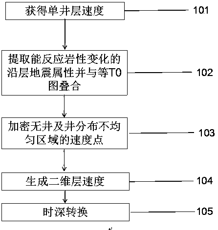
[0018] Such as figure 1 As shown, figure 1 It is a flow chart of the method for constructing a diagram of a complex fault block speed change structure in the later development stage of the present invention.

[0019] Step 101: On the basis of completing the fine horizon calibration, horizon and fault closure interpretation of the whole area, read the time value of the seismic interpretation horizon corresponding to the geological horizon of a single well with accurate horizon calibration and correct deviation, and Use the layer depth on the well and the read time value to calculate the single well layer velocity, and step 102 is entered.

[0020] Step 102: Analyze the lithological change of the study layer, extract the seismic attributes along the ...


PUM


Abstract

The invention provides a complex fault block velocity-varied structure mapping method in late development. The method comprises steps: 1, the interval velocity of a single well is acquired through a seismic interpretation horizon and a geological stratification; 2, horizon-oriented seismic attributes which can reflect lithological changes are extracted, and an attribute image and an equal T0 imageare superposed; 3, based on the principle of a consistent formation velocity at the same lithology and at the same time, velocity points of areas with no wells or with nonuniformly-distributed wellsare encrypted; 4, with the seismic interpretation horizon as a trend surface and with a fault boundary as an interpolation boundary, interpolation is carried out on the interval velocity of the singlewell, and a two-dimensional interval velocity field is built; and 5, the generated two-dimensional interval velocity grid and the equal T0 grid are multiplied for time-depth conversion, and a final structure map is obtained. The method provides accurate basic guidance for the study of a remaining oil distribution law and the development of well pattern reorganization in complex fault block fine reservoir description, a guidance role is played in late development of the reservoir of the kind, the prospect of popularization and application is broad, and economic and social benefits are remarkable.

Description

Technical field [0001] The invention relates to the field of description of complex fault block fine oil reservoirs, in particular to a method for mapping complicated fault block variable speed structures in the later stage of development. Background technique [0002] Complex fault blocks are affected by lithology, topography and structure, and fracture systems. In many areas, the vertical and horizontal velocities of the formation velocity vary greatly, and the structure mapping accuracy in the later stage of development is relatively high. Use single well average velocity or multi-well simulation The structure map of the time-depth conversion of the combined formula has a large error with the uphole, which cannot meet the accuracy requirements, and a variable speed structure is required to form the map. At present, there are many researches on variable-speed mapping methods, mainly including the interpolation of the velocity field from the well point velocity and the calculati...

Claims


Application Information

Patent Timeline
IPC IPC(8): G01V1/32
CPCG01V1/32G01V2210/48
Inventor 谭琴辉赵开连栾春华王建程会明武刚陶国秀李新宋力薛玉荣房环环孙英杰
Owner CHINA PETROLEUM & CHEM CORP
Learn More