
Bond damage detection system

A detection system and bonding technology, applied in semiconductor/solid-state device testing/measurement, electrical components, circuits, etc., can solve problems such as safety risks in corrosion operations, difficulty in identifying by human eyes, and low abnormality detection rate, etc., to avoid The effects of artificial naked eye identification of damage, short test time, and reduced difficulty

Active Publication Date: 2020-06-23
WUXI CHINA RESOURCES HUAJING MICROELECTRONICS
View PDF3 Cites 0 Cited by
  • Summary
  • Abstract
  • Description
  • Claims
  • Application Information

AI Technical Summary

Problems solved by technology

[0003] However, the above methods of detecting damage have disadvantages such as long time-consuming, difficulty in identifying minor damage by human eyes, safety risks in corrosion operation, and low abnormal detection rate.

Method used


Image

  • Bond damage detection system
  • Bond damage detection system
  • Bond damage detection system

Examples


Embodiment Construction

[0022] Reference will now be made in detail to the exemplary embodiments, examples of which are illustrated in the accompanying drawings. When the following description refers to the accompanying drawings, the same numerals in different drawings refer to the same or similar elements unless otherwise indicated. The embodiments described in the following exemplary embodiments do not represent all embodiments consistent with the present application. Rather, they are merely examples of apparatuses and methods consistent with aspects of the present application as recited in the appended claims.

[0023] The terminology used in this application is for the purpose of describing particular embodiments only, and is not intended to limit the application. As used in this application and the appended claims, the singular forms "a", "the", and "the" are intended to include the plural forms as well, unless the context clearly dictates otherwise. It should also be understood that the term ...


PUM


Abstract

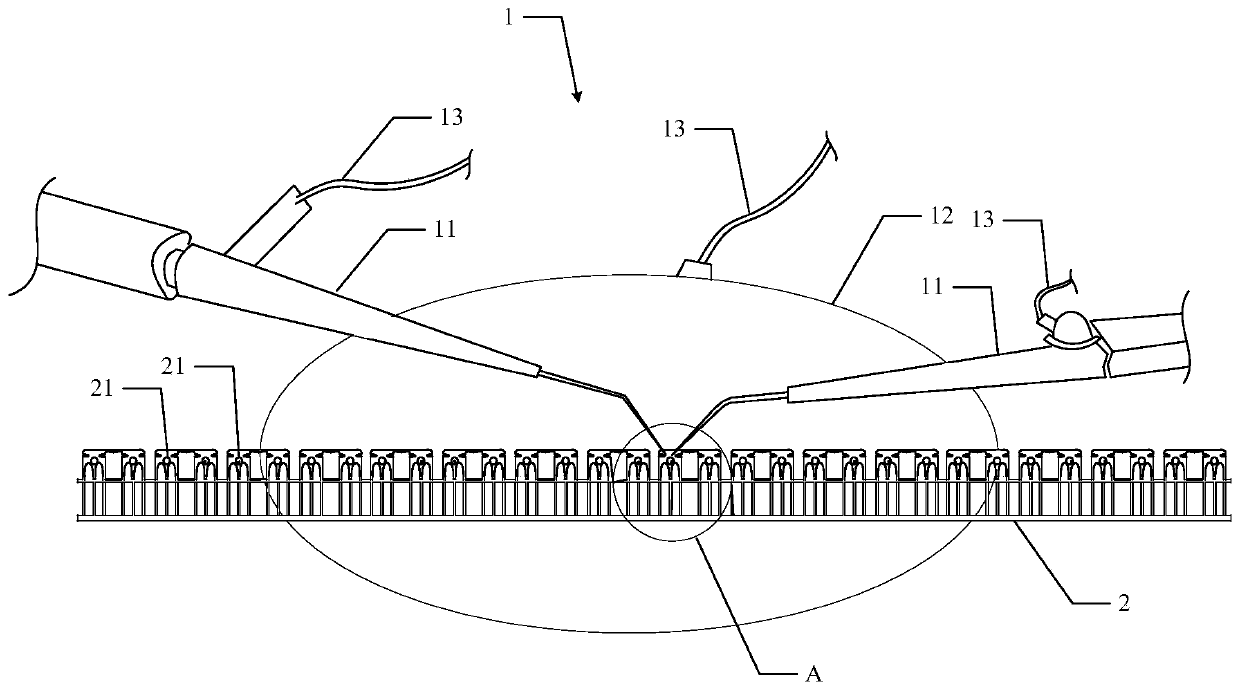
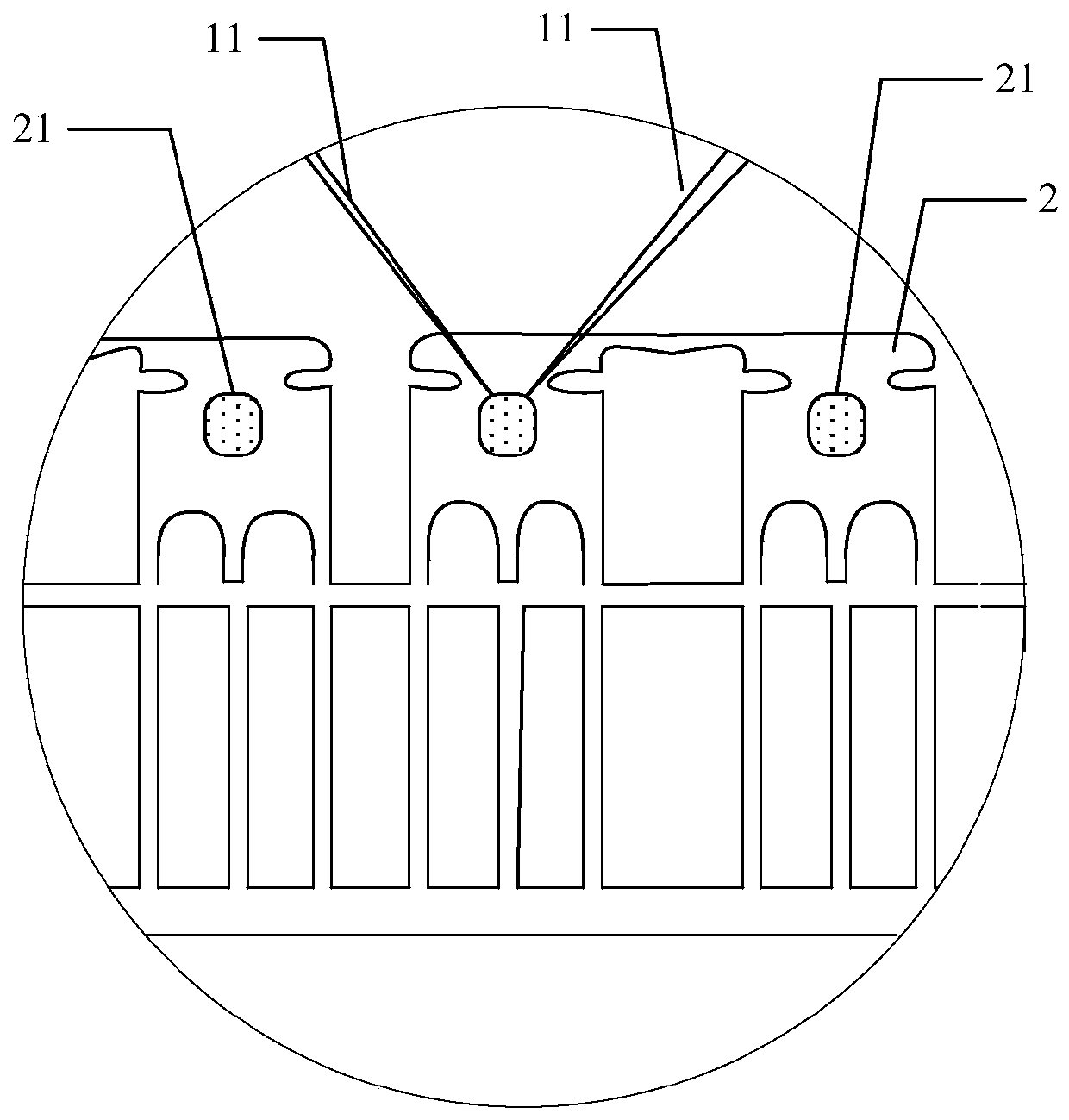
The present invention provides a bonding damage detection system. The bonding damage detection system of the invention includes a probe station and a test device which are connected with each other; wherein the probe station includes probes and a metal disk; the probes of the probe station contact with the front surface electrodes of chips to be tested; the metal disk of the probe station is electrically connected with the back surface electrodes of the chips to be tested; the probes and the metal disk are all electrically connected with the test device; and the chips to be tested are rib-uncut bonding products. During a test, the test device sets preset parameters, is used for detecting the damage related parameters of the chips to be tested through the probe station, and compares the damage related parameters with the preset parameters to determine whether bonding damage exists on the chips to be tested. Compared with the prior art, the bonding damage detection system of the presentinvention can shorten the duration of damage detection, reduce the difficulty of damage identification, avoid the safety risk of the damage identification, and improve an abnormal detection rate.

Description

technical field [0001] The present application relates to the technical field of semiconductor chip testing, in particular to a detection system for bonding damage. Background technique [0002] In the field of back-end packaging of semiconductor devices, wire-bonded products need to be monitored for bonding damage during the bonding production process. At present, the method generally adopted in the industry is to use chemical reagent corrosion method to remove the top layer metal of the bonded PAD (pad), and observe with the naked eye under a microscope whether there is any damage under the solder joint. There are two main treatment methods in the chemical reagent corrosion method: one is a strong acid plus a catalyst for chemical reaction with the sample to be tested; the other is a chemical reaction with the sample to be tested by heating the alkali solution. [0003] However, the above-mentioned damage detection methods have disadvantages such as long time-consuming, d...

Claims


Application Information

Patent Timeline
Patent Type & Authority Patents(China)
IPC IPC(8): H01L21/66
CPCH01L22/12
Inventor 唐明龙朱国平周建军
Owner WUXI CHINA RESOURCES HUAJING MICROELECTRONICS
Learn More