Method for winding polar group of valve-regulated lead acid storage battery and special apparatus for same

A technology of lead-acid batteries and pole groups, which is applied in the construction of lead-acid batteries, lead-acid batteries, battery electrodes, etc. It can solve the problem that the pole spacing of the inner ring of the pole group becomes smaller, affects the performance of the battery, and cannot guarantee the acid absorption of the plates, etc. problem, achieve the effect of improving battery performance and quality

Pending Publication Date: 2018-06-05
CAMEL GRP XIANGYANG BATTERY
View PDF7 Cites 0 Cited by
  • Summary
  • Abstract
  • Description
  • Claims
  • Application Information

AI Technical Summary

Problems solved by technology

The disadvantages are: this winding method causes the inner circle of the pole group to be wound first to receive more and more pressure during the winding process, so that the pole spacing of the inner circle of the pole group becomes smaller; the winding pressure is controlled by the air pressure. Air pressure control cannot meet the requirement of constant pressure
Since the electrode spacing of the electrode group cannot be guaranteed to be stable, the acid absorption of the electrode plate cannot be guaranteed, which affects the performance of the battery

Method used


Image

  • Method for winding polar group of valve-regulated lead acid storage battery and special apparatus for same
  • Method for winding polar group of valve-regulated lead acid storage battery and special apparatus for same
  • Method for winding polar group of valve-regulated lead acid storage battery and special apparatus for same

Examples


Embodiment Construction

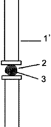
[0017] figure 1 Middle, pressure bar 1 ’ , Polar plate material 2, roll mandrel 3.

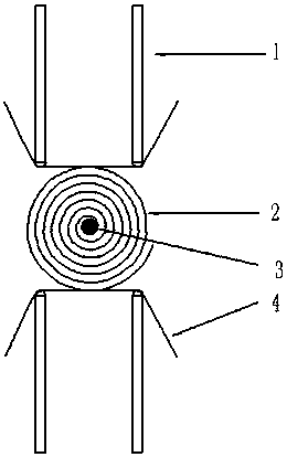
[0018] figure 2 In this case, the belt 4 circulates on the force arm 1. When the pole group is wound, the belt 4 contacts the plate material 2. The friction between the belt 4 and the plate material 2 drives the plate material 2 to rotate, and the plate material 2 drives it. The reel spindle 3 rotates. Can successfully solve the current shortcomings of continuous increase in core winding pressure during winding.

[0019] Because the tension of the belt 4 is controlled by the force arm 1 to be constant, the force acting on the plate is always in a constant state.

[0020] Each time the winding mandrel 3 completes one revolution, the motor can accurately control the rising height of the moment arm 1 within this time according to the pulse of the rotating shaft, that is, the belt 4 synchronously rises to a constant height, and this height is the pole group pole distance. This winding method can ensu...


PUM


Abstract

The invention discloses a method for winding a polar group of a valve-regulated lead acid storage battery and a special apparatus for the same. A polar plate material is fixedly arranged on a core reel; two sides of the core reel are each provided with belt hold-down mechanisms; belts of the belt old-down mechanisms perform circulatory movement on moment arms; the rotation directions of the beltsof the two belt hold-down mechanisms are opposite; the belts of the two belt old-down mechanisms are in contact with the polar plate material on the core reel respectively; the polar plate material isdriven to rotate for winding through the friction among the belts and the polar plate material; the polar plate material drives the core reel to rotate. The core reel of the special apparatus is notused as a power output device any more; the interior of the polar group can be prevented from being suffered from higher and higher winding pressure as the winding process is carried out; an equidistant spiral line principle is adopted; each circle of polar plate is guaranteed to be suffered from constant pressure in the winding process of the polar group; the space of the polar group can be guaranteed to be highly coincident; the stableness of a polar space is ensured; further, the acid absorption amount of a baffle plate is guaranteed to be constant; thus, the performance of the battery is guaranteed to be stable, and the method can be used for improving the quality of the polar group, is used for improving the performance of the battery and is applicable to industrialized production.

Description

Technical field [0001] The invention belongs to the technical field of AGM valve-regulated lead-acid batteries, and specifically relates to a valve-regulated lead-acid battery pole group winding method. Background technique [0002] In the prior art, the method of winding the battery pole group (see figure 1 Shown) is: Wrap the pole plate material 2 on the winding mandrel 3, and drive the pole plate material 2 to rotate by the rotation of the winding mandrel 3, and use the winding mandrel 3 as the winding power when winding, and at the same time outside the pole group Use lever 1 ’ A certain pressure is applied to the pole group, and the pressure rod 1 ’ The amount of applied pressure is controlled by air pressure. The disadvantage is that the winding method causes the inner ring of the pole group to be wound first to receive more and more pressure during the winding process, which makes the pole distance between the inner ring of the pole group smaller; the winding pressure is...

Claims


Application Information

Patent Timeline
Patent Type & Authority Applications(China)
IPC IPC(8): H01M4/04H01M10/12
CPCH01M4/043H01M10/121Y02E60/10Y02P70/50
Inventor 鲁义铭刘长来夏诗忠邓国强谢云清胡晓敏于坤平黄汉平杜博文黄祎
Owner CAMEL GRP XIANGYANG BATTERY
Why Eureka
Try Eureka