Glass three-dimensional columnar hole laser cutting method

A cutting method, hole laser technology, applied in the direction of laser welding equipment, welding/welding/cutting items, manufacturing tools, etc., can solve the problems of affecting laser transmittance, laser can not cut, not widely used, etc., to improve cutting efficiency , Conducive to slag discharge, reduce the effect of refraction and reflection

Inactive Publication Date: 2019-08-06
HUAZHONG UNIV OF SCI & TECH
View PDF9 Cites 21 Cited by
  • Summary
  • Abstract
  • Description
  • Claims
  • Application Information

AI Technical Summary

Problems solved by technology

There are many types of lasers, and laser cutting is more used in metals and some opaque non-metals. For transparent glass, considering the absorption rate of glass to different wavelengths of laser light, the application is still not wide enough; another problem is the laser processing. The cost is high, and if the high-efficiency processing of glass cannot be achieved, it has no advantage over traditional processing methods
Howev

Method used


Image

  • Glass three-dimensional columnar hole laser cutting method
  • Glass three-dimensional columnar hole laser cutting method
  • Glass three-dimensional columnar hole laser cutting method

Examples


Embodiment 1

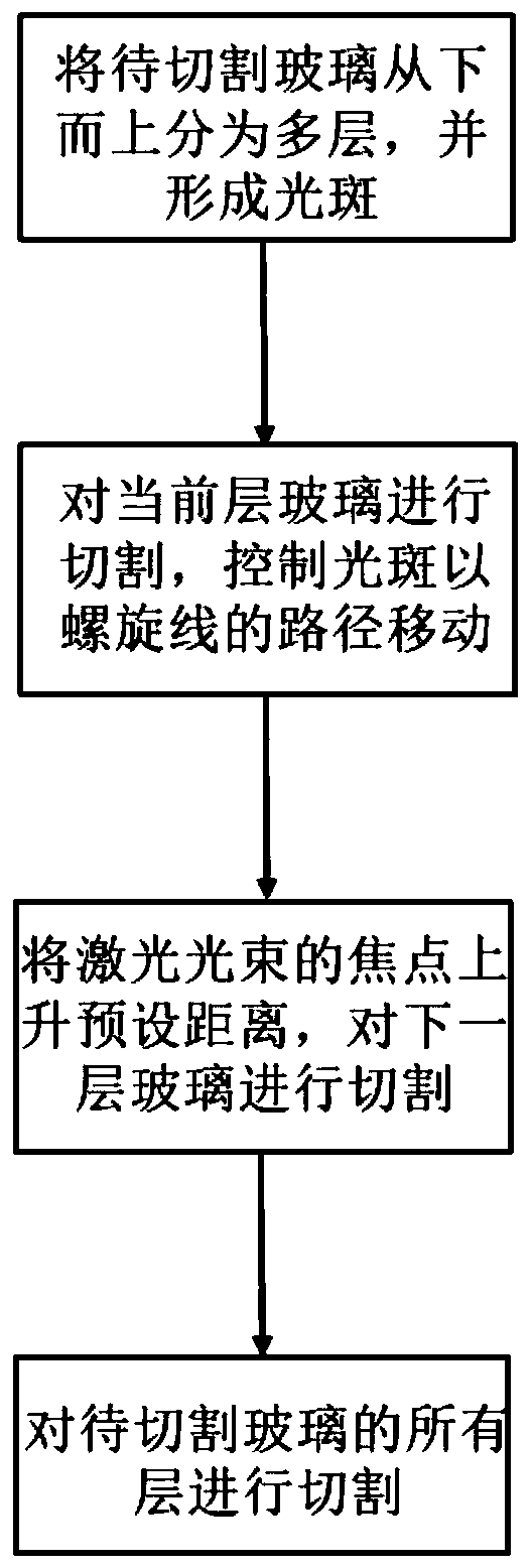
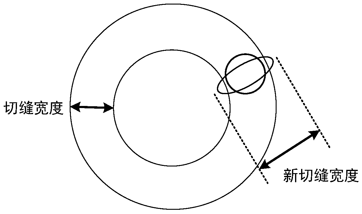
[0047] A 40W green laser is selected to emit a laser beam, which is expanded 1.5 times by the galvanometer and then focused by a telecentric field lens to form an elliptical spot. A cylindrical hole with a diameter of 10mm is cut on a float glass with a thickness of 2.5mm, and the scanning is set. The speed is 320mm / s, the rising distance of each layer is 0.8 times the depth of focus, the width of the helix is ​​0.47mm, and the overlap rate of the helix is ​​70%. By adopting the above method parameters, a three-dimensional columnar hole with high incision quality can be obtained efficiently.

Embodiment 2

[0049] A 20W green laser is selected to emit a laser beam, which is expanded 3 times by a galvanometer and then focused by a telecentric field lens to form an elliptical spot. A cylindrical hole with a diameter of 10mm is cut on a float glass with a thickness of 2.5mm, and the scan is set. The speed is 300mm / s, the rising distance of each layer is 0.9 times the depth of focus, the width of the helix is ​​0.5mm, and the overlap rate of the helix is ​​80%. By adopting the above method parameters, a three-dimensional columnar hole with high incision quality can be obtained efficiently.

Embodiment 3

[0051] A 35W green laser is selected to emit a laser beam, which is expanded 5 times by the galvanometer and then focused by a telecentric field lens to form an elliptical spot. A cylindrical hole with a diameter of 10mm is cut on the embossed glass with a thickness of 2.5mm. First, the glass Evenly spray transparent liquid on the upper surface to pave it, and set the scanning speed to 150mm / s, the rising distance of each layer is 0.5 times the focal depth, the width of the helix is ​​0.4mm, and the overlap rate of the helix is ​​65%. By adopting the above method parameters, a three-dimensional columnar hole with high incision quality can be efficiently obtained.


PUM

PropertyMeasurementUnit
Widthaaaaaaaaaa
Poweraaaaaaaaaa

Abstract

The invention belongs to the technical field of laser processing and particularly discloses a glass three-dimensional columnar hole laser cutting method which comprises the following steps: dividing to-be-cut glass into a plurality of layers from bottom up, and focusing a laser beam on the surface of the to-be-cut glass to form a light spot; controlling the light spot to move on the current-layerglass in a spiral line path, and finally cutting to form a circular ring groove on the current-layer glass; after cutting the current-layer glass, ascending the focal point of the laser beam by a preset distance, and then cutting the next-layer glass; and repeating the operations until cutting all layers of the to-be-cut glass to finish the glass three-dimensional columnar hole laser cutting. According to the glass three-dimensional columnar hole laser cutting method, the to-be-cut glass is cut from bottom up to ensure that the laser beam works within the effective cutting range so as to facilitate slag discharging while improving the cutting efficiency of the laser beam; and in addition, the light spot is controlled to move in the spiral line path on each layer of glass so as to fully cutthe glass, and slag discharging is facilitated.

Description

technical field [0001] The invention belongs to the technical field of laser processing, and more specifically relates to a laser cutting method for three-dimensional columnar holes in glass. Background technique [0002] Glass is one of the most commonly used materials in daily life, and its processing method is also a concern in the industry. With the continuous development of industry, its processing method is also constantly innovating. The mainstream float glass and patterned glass in the photovoltaic industry mainly use diamonds and diamond wires for mechanical cutting, which is not only inefficient, but also the quality of the cut is not high enough, and the cutting tool wears seriously during the cutting process, and has a certain degree of pollution to the environment. [0003] Because the laser has the advantages of high brightness, high directionality, high monochromaticity and high coherence, it is suitable for the processing of glass. Raise to the gasification ...

Claims


Application Information

Patent Timeline
IPC IPC(8): B23K26/38B23K26/402
CPCB23K26/38B23K26/402B23K2103/54
Inventor 荣佑民黄禹龚时华李文元陈春梦
Owner HUAZHONG UNIV OF SCI & TECH
Why Eureka
Try Eureka