Two-way single-direction speed regulating valve

A one-way speed control valve and speed control valve technology, applied in the field of hydraulic valves, can solve the problems of increasing external leakage links, complex structure, difficult manufacturing, etc., and achieve the effect of constant flow, few parts and compact structure

Active Publication Date: 2018-06-12
江苏艾伦弗罗机械制造有限公司
View PDF9 Cites 2 Cited by
  • Summary
  • Abstract
  • Description
  • Claims
  • Application Information

AI Technical Summary

Problems solved by technology

Although this one-way speed control valve can realize one-way stepless speed regulation of the working parts, it needs a higher pressure to open the slide valve when the working cylinder returns quickly, so it is not suitable for use in low-pressure circuits.
At the same time, because the throttling mechanism and the slide valve are separately arranged in the intersecting hole in the valve body, the speed regulating valve has a large volume and a very complicated structure, and requires several more process holes, which increases the external leakage link and is difficult to manufacture. High cost, subject to bulky shape during use

Method used


Image

  • Two-way single-direction speed regulating valve
  • Two-way single-direction speed regulating valve

Examples


Embodiment Construction

[0016] The present invention will be further described in detail below in conjunction with the accompanying drawings and embodiments.

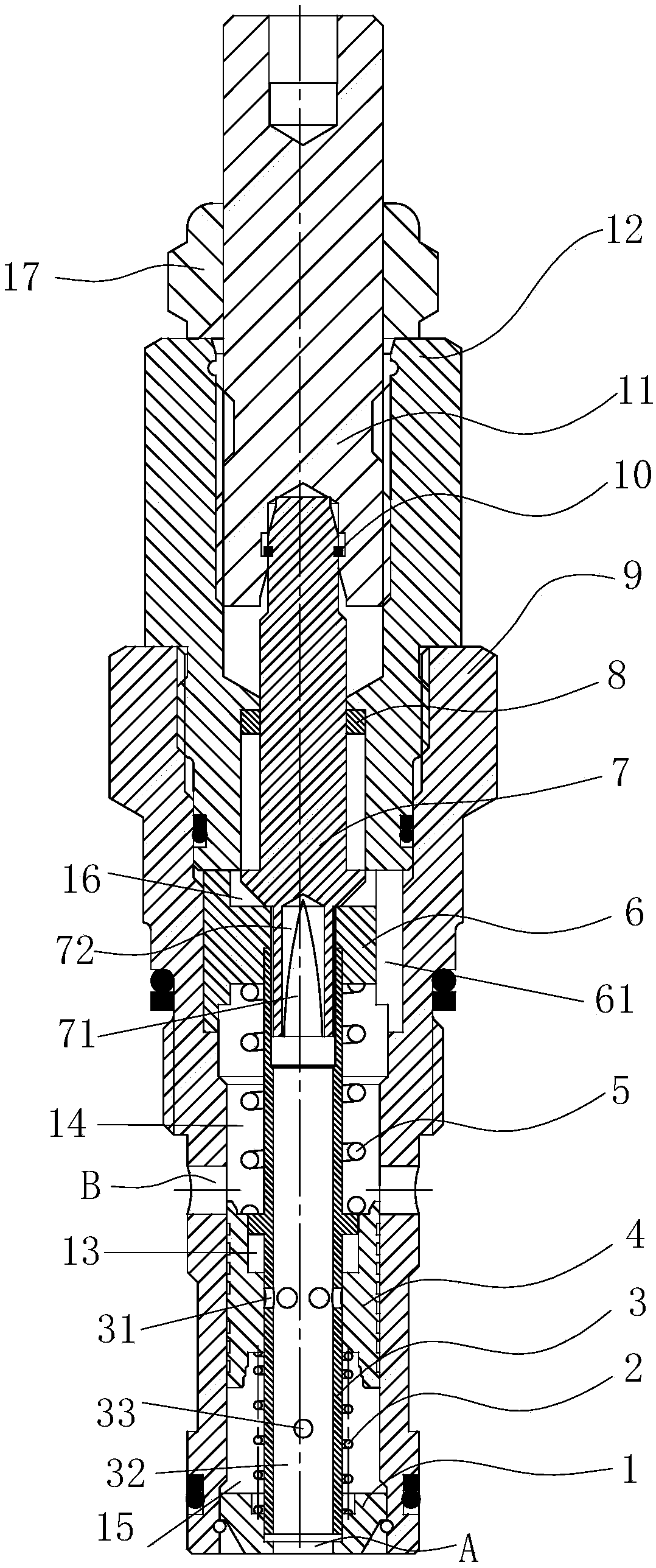
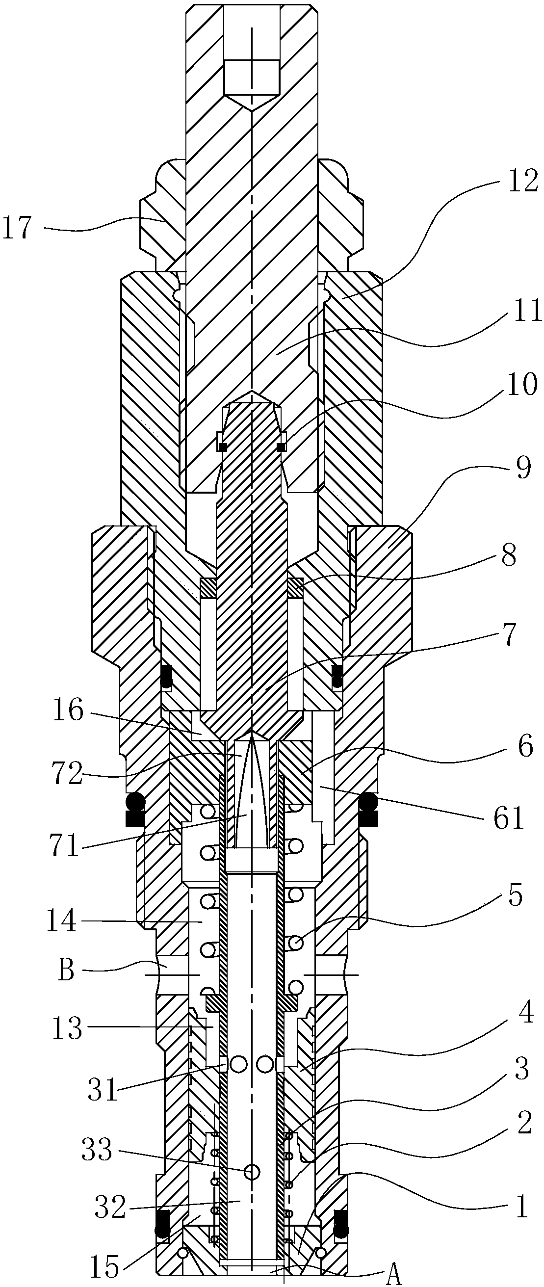
[0017] Such as Figure 1~2 Shown is a preferred embodiment of the present invention.

[0018] A two-way one-way speed regulating valve, including a valve body 9, a spring seat 1 with a first oil port A is fixed in the lower port of the valve body 9, and a second oil port B is opened on the peripheral wall of the valve body 9 ;

[0019] The valve seat 6 is fixed in the valve body 9, and a throttling cavity 16 is formed above the valve seat 6;

[0020] A bushing 3 with a through hole 32, the upper end of the bushing 3 is supported on the valve seat 6, the lower end of the bushing 3 is supported on the spring seat 1 and the first oil port A is communicated with the through hole 32 of the bushing 3 .

[0021] The pressure compensating valve core 4 with a stepped hole is sheathed on the outer periphery of the bushing 3 and can slide up and down...


PUM


Abstract

The invention relates to a two-way single-direction speed regulating valve. The two-way single-direction speed regulating valve is characterized in that a valve body, a spring base with a first oil opening, a valve base, a bush with a through hole, a pressure compensating valve element, a first spring cavity, a second spring cavity, a throttling valve element, a driving structure are included, wherein a second oil opening is formed in the peripheral wall of the valve body; the periphery of the bush is sleeved with the pressure compensating valve element, the pressure compensating valve elementcan vertically slide along the bush, a through-flow cavity is formed in a large hole part of a step hole of the pressure compensating valve element, and a through-flow hole is formed in the peripheral wall of the bush. A first spring is arranged in the first spring cavity, and a damping hole is formed in the peripheral wall of the bush. A second spring is arranged in the second spring cavity, andthe second oil opening communicates with the second spring cavity. A through-flow groove is formed in the valve base. The throttling valve element can vertically slide, an adjusting cavity is formedin the bottom of the throttling valve element, and a throttling valve is formed in the peripheral wall of the adjusting cavity. The driving structure is used for driving the throttling valve element to vertically slide. The two-way single-direction speed regulating valve has the function of a one-way valve, and it can be guaranteed that the output flow of the second opening is kept consistent; andthe number of involved components is small, and the structure is compact.

Description

technical field [0001] The invention belongs to the technical field of hydraulic valves, in particular to a two-way one-way speed regulating valve. Background technique [0002] The one-way speed regulating valve is widely used in the speed control of the mechanical hydraulic system, so that the working parts can realize the one-way stepless speed regulation independent of the load. The existing traditional one-way speed regulating valve comprises a valve body, an adjusting hand wheel, a flow adjusting rod, a throttle valve core, a slide valve, an adjusting screw seat and a spring seat. The hydraulic oil enters the throttling cavity from the pump station through the oil inlet passage, and the throttling mechanism composed of the throttling valve core, the flow adjustment rod, the adjustment handwheel and the adjustment screw seat, after steplessly adjusting the flow rate, flows through the oil outlet passage It enters the working cylinder, so that the speed of the working c...

Claims


Application Information

Patent Timeline
Patent Type & Authority Applications(China)
IPC IPC(8): F15B13/02
Inventor 邵立坤
Owner 江苏艾伦弗罗机械制造有限公司
Why Eureka
Try Eureka