Pipe connector sealing ring
A technology of sealing rings and connectors, applied in non-detachable pipe connections, flange connections, sleeve/socket connections, etc., can solve problems such as delays in production cycles, waste, logistics waste, etc., to save high costs and reduce Low cost, high economic benefit effect
- Summary
- Abstract
- Description
- Claims
- Application Information
AI Technical Summary
Problems solved by technology
Method used
Image
Examples
Embodiment 1
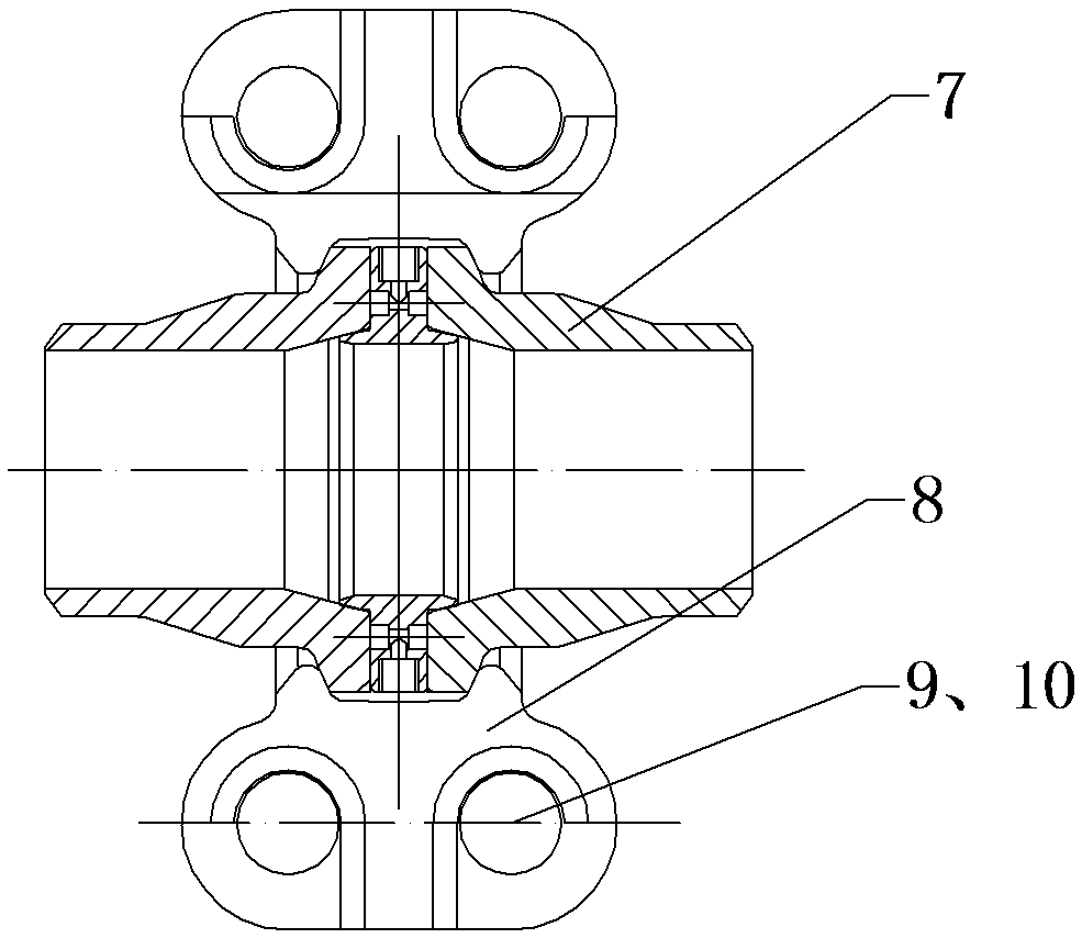
[0053] like figure 1 As shown, the pipe connector of the Kalan method is composed of left and right symmetrical pipe connectors 7, which are clamped together by ferrules 8, and the bolts 9 or nuts 10 are tightened, so that the distance between the two ferrules 8 is shortened, and the two pipes are connected. The parts 7 are squeezed by the ferrule 8 and come close to each other, and clamp the sealing ring of the pipe connector installed between the pipe connecting parts 7; it plays a role of sealing. The pipe connector sealing ring can also be as Figure 4 As shown, it is used in pipe connectors with flange connection. The pipe connector 7 has a flange, and by tightening the bolts 9 or nuts 10, the distance between the two pipe connectors 7 is shortened, and the pipe connector sealing ring installed between the pipe connectors 7 is clamped; to the sealing effect.
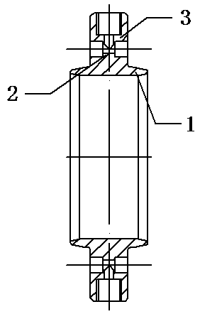
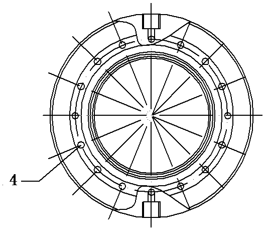
[0054] like figure 2 As shown, the sealing ring of the pipe connector includes a two-part structure of the l...
Embodiment 2
[0062] The glue injection part 3, the connecting part 2 and the lip part 1 in the embodiment 1 are provided integrally; as Figure 16 In this embodiment shown, several examples in which the glue injection part 3 , the connecting part 2 and the lip part 1 are provided separately are listed; those skilled in the art can also make changes and combinations. Figure 16 The sealing ring of the middle pipe connector is divided into three rings: lip part 1, connecting part 2 and glue injection part 3, and the three rings are nested together in sequence; the connection part 2 makes the glue injection part 3 of the outer ring and the lip part of the inner ring The distance between 1 remains fixed; the thickness of the ring of the connecting part 2 is smaller than the thickness of the ring of the lip 1 and the injection part 3, and a cavity is formed on both sides of the connecting part 2 as a plugging container for the plugging glue. slot. can also be like Figure 17 As shown, the con...
Embodiment 3
[0065] The high-pressure self-tightening flange has been improved, and a leak-stopping ring is added. The leak-stopping ring is a T-shaped ring or an I-shaped ring, and the socket on one side is provided with a glue injection hole. When in use, a certain cavity is formed between the plugging ring and the socket, and a glue injection hole is provided at the position corresponding to the cavity. When leakage occurs, a certain gap is formed between the leak plugging ring and the socket directly through the glue injection hole. The cavity is treated with glue injection to form an annular sealing rubber ring, which plays the role of plugging. Glue to achieve the effect of sealing on both sides.
[0066] There is at least one glue injection hole on the plugging ring, and the glue injection hole is connected with the glue injection valve through the gap between two kalans, or a through hole is provided on the kalan, communicated with the glue injection hole, and connected with the gl...
PUM
 Abstract
Description
Claims
Application Information
 - R&D
- Intellectual Property
- Life Sciences
- Materials
- Tech Scout
- Unparalleled Data Quality
- Higher Quality Content
- 60% Fewer Hallucinations
Browse by: Latest US Patents, China's latest patents, Technical Efficacy Thesaurus, Application Domain, Technology Topic, Popular Technical Reports.
© 2025 PatSnap. All rights reserved.Legal|Privacy policy|Modern Slavery Act Transparency Statement|Sitemap|About US| Contact US: help@patsnap.com


