
An automatic pick-and-place measuring device

A measuring device and automatic pick-and-place technology, applied in the field of optical testing, can solve the problems of lens rotation, cost increase, and no solution proposed, so as to avoid errors, reduce labor costs, and reduce workload.

Active Publication Date: 2020-02-07
NINGBO SUNNY AUTOMOTIVE OPTECH
View PDF9 Cites 0 Cited by
  • Summary
  • Abstract
  • Description
  • Claims
  • Application Information

AI Technical Summary

Problems solved by technology

Although the patent can perform multi-angle testing on the lens, the patent cannot automatically rotate the lens, but must be manually rotated by the tester, resulting in an increase in cost
[0007] For the above problems, no effective solution has been proposed

Method used


Image

  • An automatic pick-and-place measuring device
  • An automatic pick-and-place measuring device
  • An automatic pick-and-place measuring device

Examples


Embodiment Construction

[0035] The description of this illustrative embodiment should be taken in conjunction with the accompanying drawings, which should be considered a part of this complete specification. In the drawings, the shapes or thicknesses of the embodiments may be exaggerated and marked for simplification or convenience. Furthermore, parts of each structure in the drawings will be described separately. It should be noted that elements not shown in the drawings or described in words are forms known to those of ordinary skill in the art.

[0036] The descriptions of the embodiments here, any references to directions and orientations are just for convenience of description, and should not be construed as any limitation to the protection scope of the present invention. The following descriptions of the preferred embodiments involve combinations of features, which may exist independently or in combination, and the present invention is not particularly limited to the preferred embodiments. The...


PUM


Abstract

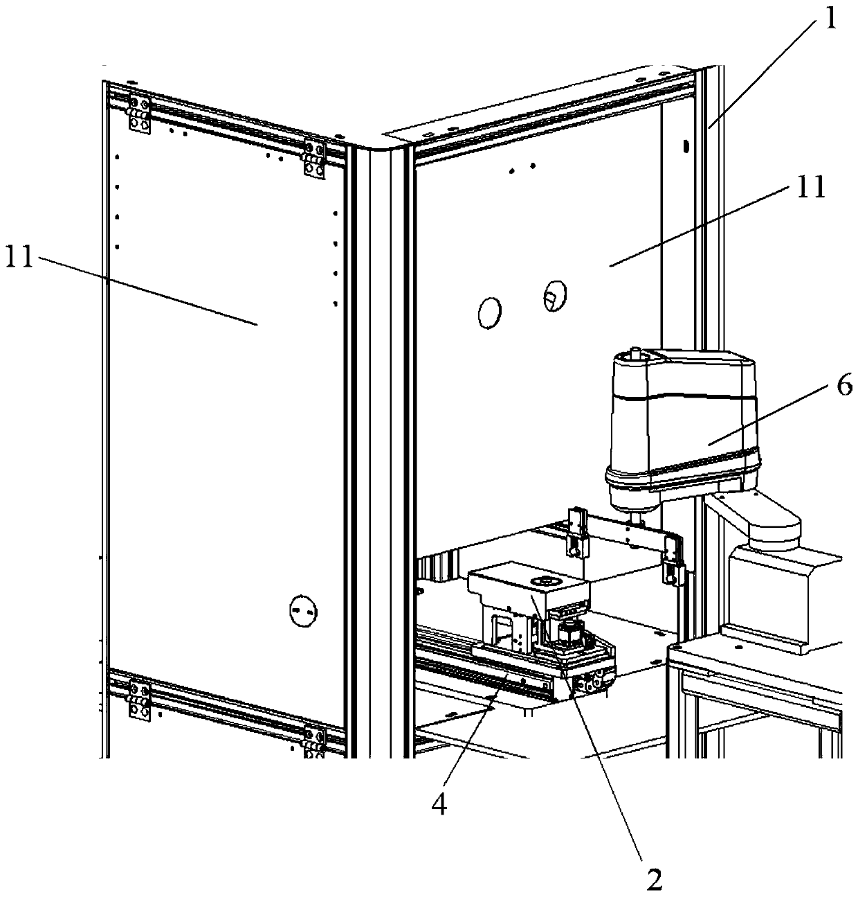
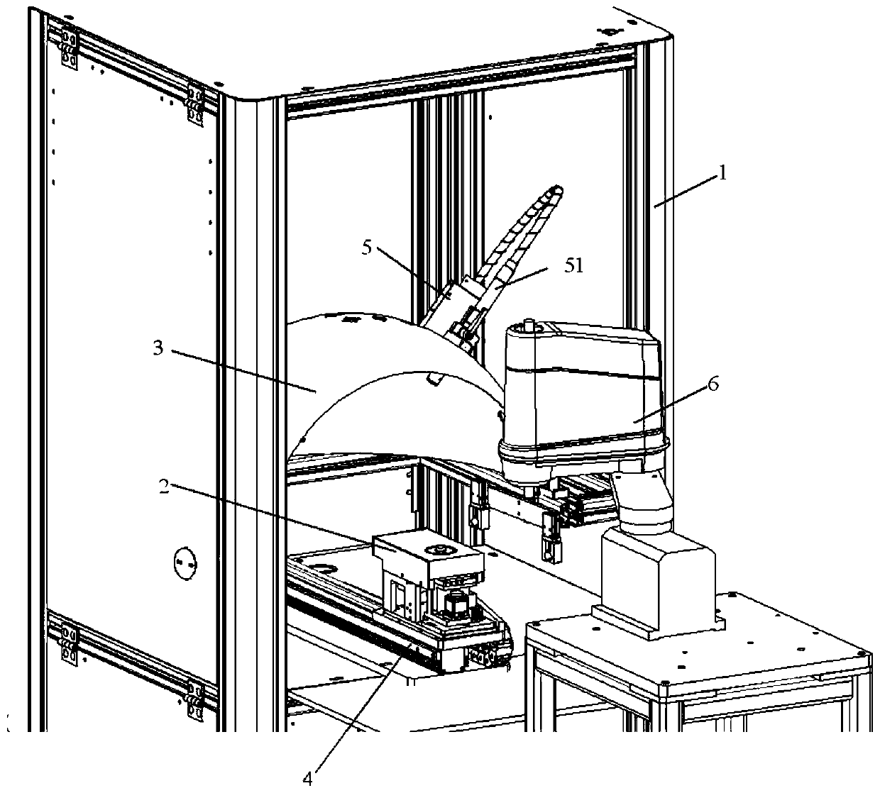
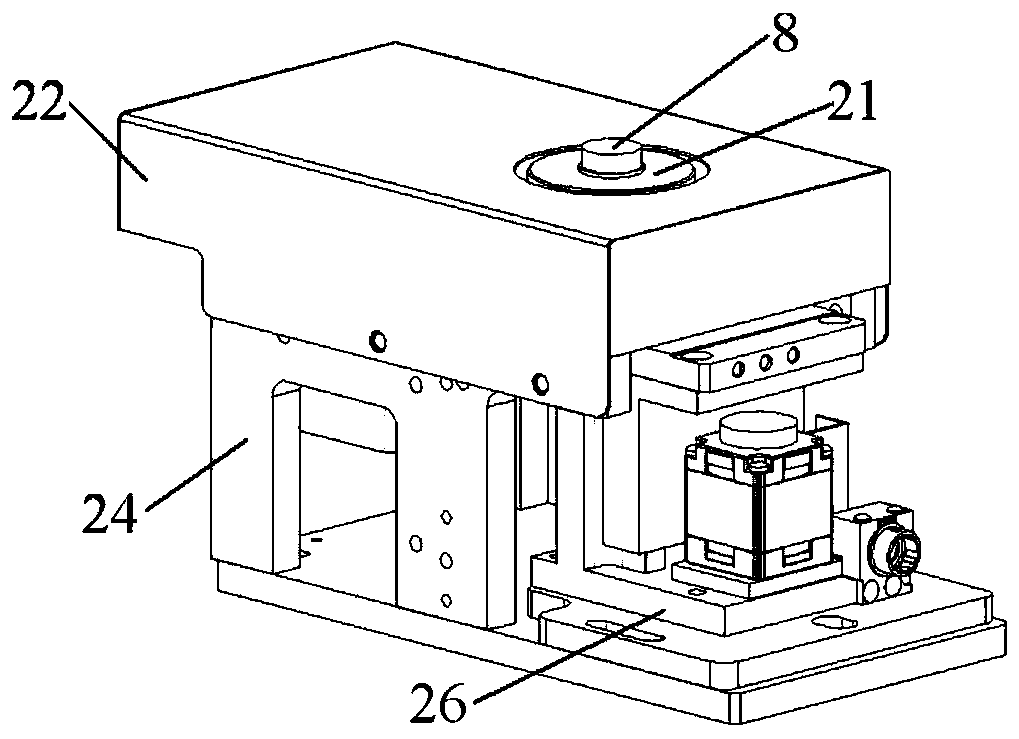
The invention discloses a measuring device with an automatic picking and placing function. The device comprises a rack, a rotating mechanism, a curtain mechanism, a movement module and a lighting mechanism, wherein the rotating mechanism, the curtain mechanism, the movement module and the lighting mechanism are installed on the rack, the movement module comprises a sliding rail, the rotating mechanism is installed on the sliding rail and moves along the sliding rail, the rotating mechanism comprises a lens installation part and a rotating device, the lens installation part is used for installing a lens to be tested, and the rotating device is used for driving the lens to be tested to rotate; the curtain mechanism is arranged at one side of one end part of the sliding rail; and the lightingmechanism comprises a light source, and the light source is arranged in a mode of being matched with the curtain mechanism. The device can automatically rotate the tested lens in the testing process,thereby reducing the workload, reducing the labor cost, further being capable of improving the control precision for the rotating angle, and avoiding an error brought about by the manual rotation. Inaddition, a good test environment can be provided for lens testing through adopting the curtain mechanism.

Description

technical field [0001] The present invention relates to the field of optical testing, and in particular, to an automatic pick-and-place measuring device. Background technique [0002] When the camera lens forms a real image of an object, in addition to the imaging light, there are other non-imaging rays that diffuse on the image surface of the optical system. These non-imaging rays are called stray light (also called stray light). Stray light usually comes from radiation sources outside the system, internal radiation sources, and non-imaging light energy from scattering surfaces, such as reflected light from various refractive surfaces such as optical components and structural parts, reflected light from the inner wall of the instrument, diffuse reflection of the lens itself, or The reflection of the lens barrel may cause stray light. In addition, the problem of stray light may also occur due to dust contamination of optical parts, damage to optical components, glue leakage,...

Claims


Application Information

Patent Timeline
Patent Type & Authority Patents(China)
IPC IPC(8): G01M11/00
CPCG01M11/00
Inventor 鲍远刚毛冬冬范立权朱金献
Owner NINGBO SUNNY AUTOMOTIVE OPTECH
Learn More