Vehicle-mounted vehicle exhaust monitoring device

A technology for vehicle exhaust and monitoring devices, which is applied in the direction of measuring devices, power devices, and gas intake of power devices, and can solve the problems of inability to monitor real-time vehicle exhaust

Inactive Publication Date: 2018-06-12
NORTHEAST FORESTRY UNIVERSITY
View PDF6 Cites 7 Cited by
  • Summary
  • Abstract
  • Description
  • Claims
  • Application Information

AI Technical Summary

Problems solved by technology

[0003] In order to solve the problem that the driver cannot monitor the exhaust gas of the vehicle in real time during the running of the vehicle, the present invention further proposes a vehicle exhaust monitoring device

Method used


Image

  • Vehicle-mounted vehicle exhaust monitoring device
  • Vehicle-mounted vehicle exhaust monitoring device
  • Vehicle-mounted vehicle exhaust monitoring device

Examples


specific Embodiment approach 1

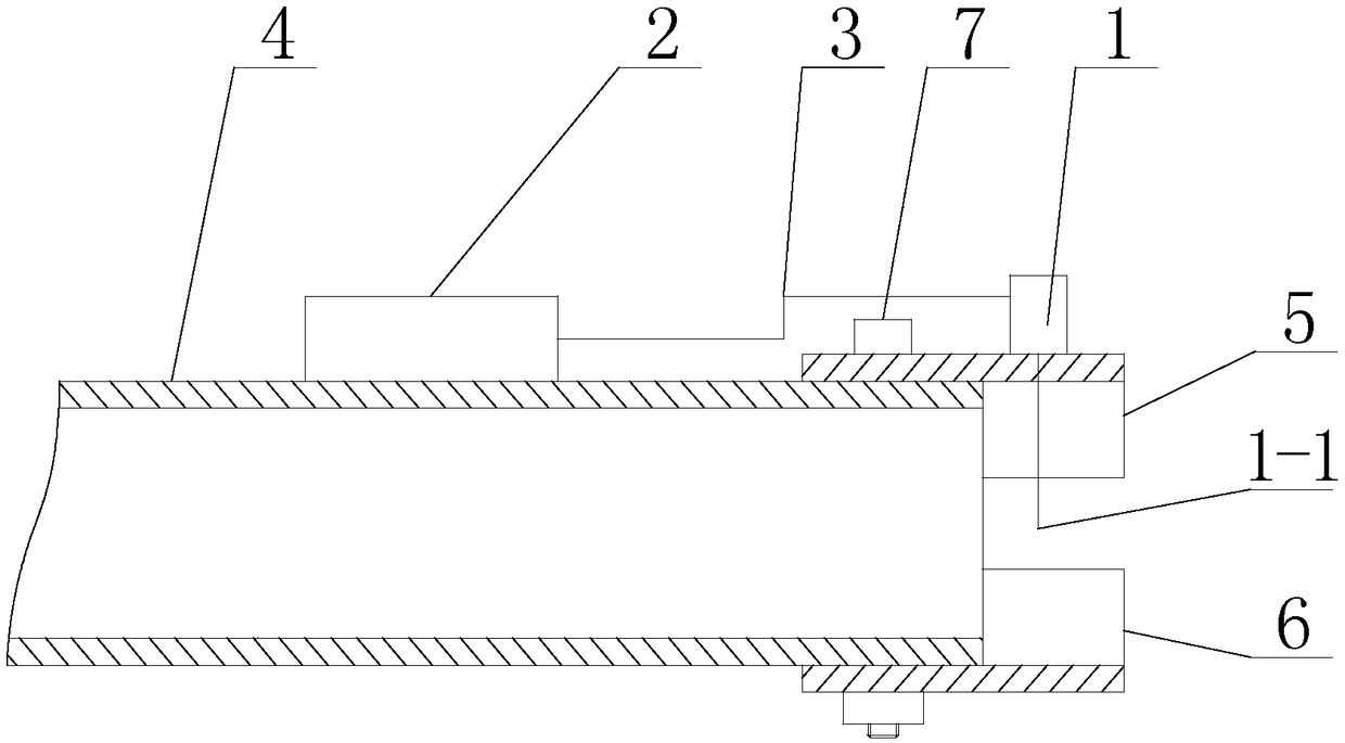
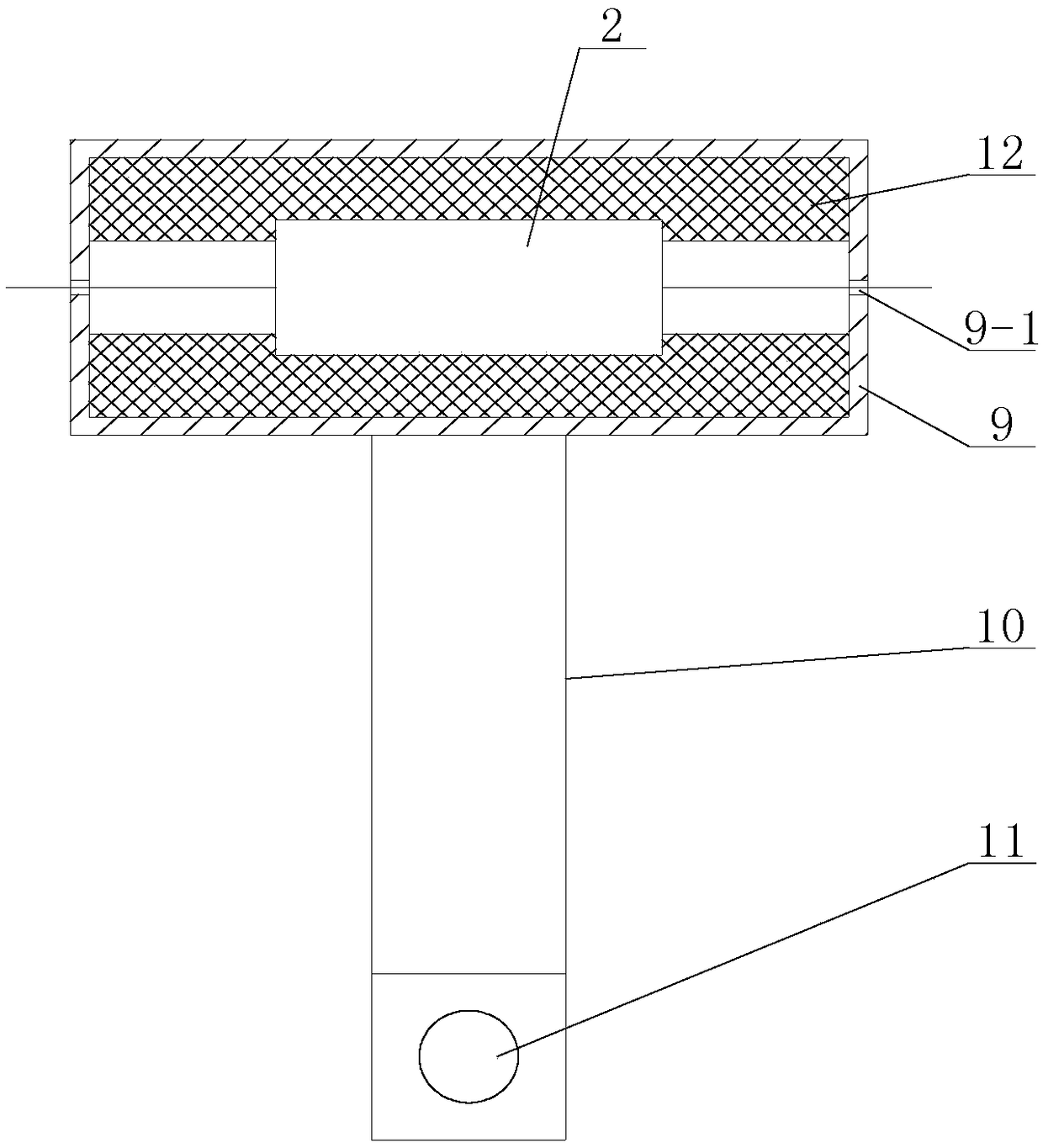
[0018] Specific implementation mode one: combine Figure 1 to Figure 4 Describe this embodiment, a kind of vehicle exhaust monitoring device described in this embodiment comprises fixing mechanism, automobile exhaust detector 1, data transmitter 2, data line 3 and vehicle data display, and automobile exhaust detector 1 is installed by described fixing mechanism At the mouth of the automobile exhaust pipe 4, the probe 1-1 of the automobile exhaust gas detector 1 is arranged at the center of the nozzle of the automobile exhaust pipe 4, and the automobile exhaust detector 1 is connected with the data transmitter 2 through the data line 3, and the data is transmitted Device 2 is connected with the described on-board data display device that is arranged in the driver's compartment by line.

specific Embodiment approach 2

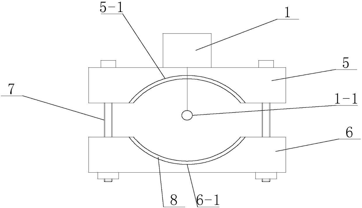
[0019] Specific implementation mode two: combination Figure 1 to Figure 4 Describe this embodiment, the fixing mechanism of a vehicle exhaust monitoring device described in this embodiment includes an upper clamping block 5, a lower clamping block 6 and two locking bolts 7, and the upper clamping block 5 and the lower clamping block 6 are from top to bottom The bottom is arranged in sequence, and the two ends of the upper clamping block 5 are connected with the two ends of the lower clamping block 6 through two locking bolts 7 . The nozzle of the automobile exhaust pipe 4 is placed between the upper clamping block 5 and the lower clamping block 6, and two locking bolts 7 make the upper clamping block 5 and the lower clamping block 6 tighten the automobile exhaust pipe 4. Other components and connections are the same as those in the first embodiment.

specific Embodiment approach 3

[0020] Specific implementation mode three: combination Figure 1 to Figure 4 Describe this embodiment, the lower surface of the upper clamping block 5 of a vehicle exhaust gas monitoring device described in this embodiment is provided with a concave first arc-shaped curved surface 5-1, and the upper surface of the lower clamping block 6 is provided with a concave The second curved surface 6-1. Such setting can increase the contact area between the upper clamping block 5 and the lower clamping block 6 and the outer wall of the automobile exhaust pipe 4, and improve the clamping firmness. Other components and connections are the same as those in the second embodiment.


PUM


Abstract

The invention relates to an exhaust monitoring device, and in particular to a vehicle-mounted vehicle exhaust monitoring device. The invention is aimed at solving the problem that a driver cannot monitor vehicle exhaust in real time as a vehicle runs. The vehicle-mounted vehicle exhaust monitoring device comprises a fixing mechanism, a vehicle exhaust detector, a data transmitter, a data wire, anda vehicle-mounted data display, the vehicle exhaust detector is mounted at the orifice of a vehicle exhaust pipe through the fixing mechanism, a probe of the vehicle exhaust detector is arranged in the center of the orifice of the vehicle exhaust pipe, the vehicle exhaust detector is connected to the data transmitter through the data wire, and the data transmitter is connected to the vehicle-mounted data display arranged in the cab through the wires. The invention belongs to the field of environmental protection.

Description

technical field [0001] The invention relates to a tail gas monitoring device, in particular to a vehicle tail gas monitoring device, which belongs to the field of environmental protection. Background technique [0002] With the improvement of people's living standards, cars have become one of the indispensable means of transportation in our lives, and more and more people and families buy private cars as a means of transportation for travel. However, the increase in the number of automobiles has exacerbated the deterioration of our surrounding environment, especially the exhaust gas generated during the driving of automobiles, which has seriously polluted the air environment. Although my country has strict regulations on vehicle exhaust emission standards, drivers cannot monitor the quality of vehicle exhaust in motion. Contents of the invention [0003] In order to solve the problem that the driver cannot monitor the vehicle exhaust in real time during the running of the...

Claims


Application Information

Patent Timeline
Patent Type & Authority Applications(China)
IPC IPC(8): G01N33/00B60K13/04
CPCB60K13/04G01N33/0004
Inventor 李冰詹长书马丹王娜陈萌吕景亮
Owner NORTHEAST FORESTRY UNIVERSITY
Why Eureka
Try Eureka