Aerator impeller

An aerator and impeller technology, which is applied in fish farming, application, animal husbandry, etc., can solve the problems of increased energy consumption of aerators, low oxygen melting efficiency, and small water volume, so as to increase volume and improve oxygen melting Efficiency, the effect of offsetting the buoyancy of the water body

Inactive Publication Date: 2018-06-15
GUIGANG HOUSHUN INFORMATION TECH CO LTD
View PDF6 Cites 0 Cited by
  • Summary
  • Abstract
  • Description
  • Claims
  • Application Information

AI Technical Summary

Problems solved by technology

The structure of the impeller in the prior art is relatively simple, and the impeller blades all adopt straight blades. When the blades rotate, the water body will generate greater resistance, which will increase the energy consumption of the aerator, and the volume of the driven water body is small, and the oxygen melting efficiency is low.

Method used


Image

  • Aerator impeller
  • Aerator impeller
  • Aerator impeller

Examples


Embodiment Construction

[0017] Now do further detailed explanation in conjunction with accompanying drawing.

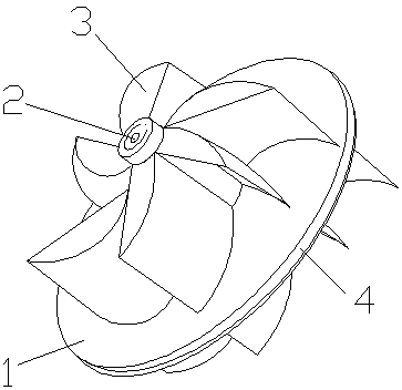
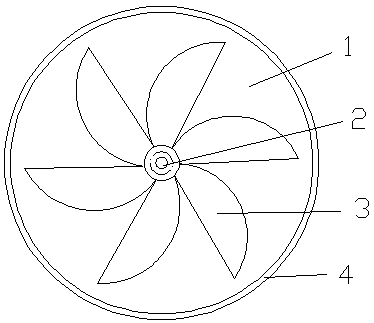
[0018] Such as Figure 1-3 As shown, an aerator impeller includes a wheel disc 1 and a wheel shaft 2, the wheel shaft 2 is arranged at the center of the wheel disc 1, the wheel shaft 2 is provided with a vane 3, and the wheel disc 1 is used as a side wall of the vane 3 .

[0019] The roulette 1 is circular, and the edge 4 of the roulette 1 protrudes outward to form a conical surface.

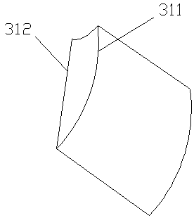
[0020] The bottom edge 311 of the vane 3 is arc-shaped, and the edge 312 of the vane mouth is straight, so that the vane 3 forms a semi-arcuate blade.

[0021] The number of said vanes 3 is 4-6, which are regularly arranged on the wheel shaft 2 and the wheel disc 1 .

[0022] Both sides of the wheel disc 1 are provided with vanes 3, and form a plane symmetrical structure with the wheel disc 1 as a plane.

[0023] The impeller is made of hard plastic.

[0024] The above is only a preferred embodiment of th...


PUM


Abstract

The invention discloses an aerator impeller. The impeller comprises a wheel plate and a wheel shaft; the wheel shaft is arranged in the center of the wheel plate; the wheel shaft is provided with wheel vanes; the wheel plate is used as a side wall of one edge of each wheel vane; and the bottom edge of each wheel vane is an arc-shaped structure, so that the impeller conforms to the law of a water flow when rotating for aeration, the area of resistance generated by the impeller and the front surface of a water body is reduced, and the wheel vanes have volumes. The aerator impeller provided by the invention can effectively offset a part of water body resistance and save energy sources; and meanwhile, the aerator impeller increases a volume of the water body with dissolved oxygen in unit time,and improves the oxygen dissolving efficiency.

Description

technical field [0001] The invention relates to an aerator accessory, in particular to an aerator impeller. Background technique [0002] The impeller of the aerator is a part installed on the aerator to stir the water to melt oxygen. Without this part, the aeration function cannot be provided. Nowadays, the density of aquaculture is relatively high, and the demand for oxygen in the water body is also large. Each aquaculture pond needs to be equipped with several aerators, which consumes a lot of energy every day and increases the cost for farmers. [0003] In terms of how to save energy, the problem is basically attributed to the engine or other driving parts of the aerator, and a lot of cost is invested in research on these parts, but there is relatively little research on the impeller. The structure of the impeller in the prior art is relatively simple, and the blades all adopt straight blades. When the blades rotate, the water body will generate greater resistance, whic...

Claims


Application Information

Patent Timeline
Patent Type & Authority Applications(China)
IPC IPC(8): A01K63/04
CPCA01K63/042
Inventor 不公告发明人
Owner GUIGANG HOUSHUN INFORMATION TECH CO LTD
Why Eureka
Try Eureka