An anti-pull suction bucket foundation and its installation method

An installation method and suction bucket technology, which are applied in infrastructure engineering, construction, sheet pile walls, etc., can solve the problems of large foundation sinking resistance, maximum negative pressure sinking depth limitation, and sinking difficulty, etc. Achieve the effect of increasing the self-weight sinking depth, reducing the sinking resistance, and reducing the sinking resistance.

Active Publication Date: 2019-10-29
HOHAI UNIV
View PDF6 Cites 2 Cited by
  • Summary
  • Abstract
  • Description
  • Claims
  • Application Information

AI Technical Summary

Problems solved by technology

[0003] In order to solve the problem that the improvement of the uplift bearing capacity of the traditional suction bucket foundation is limited by the distance between buckets and the maximum negative pressure sinking depth, as well as the defects of large penetration resistance and difficult sinking of the pullout suction bucket foundation, the invention discloses an anti-lift The specific technical scheme of pulling out the suction bucket foundation and its installation method is as follows:

Method used


Image

  • An anti-pull suction bucket foundation and its installation method
  • An anti-pull suction bucket foundation and its installation method
  • An anti-pull suction bucket foundation and its installation method

Examples


Embodiment Construction

[0027] The present invention will be further explained below in conjunction with the accompanying drawings and specific embodiments. It should be understood that the following specific embodiments are only used to illustrate the present invention but not to limit the scope of the present invention.

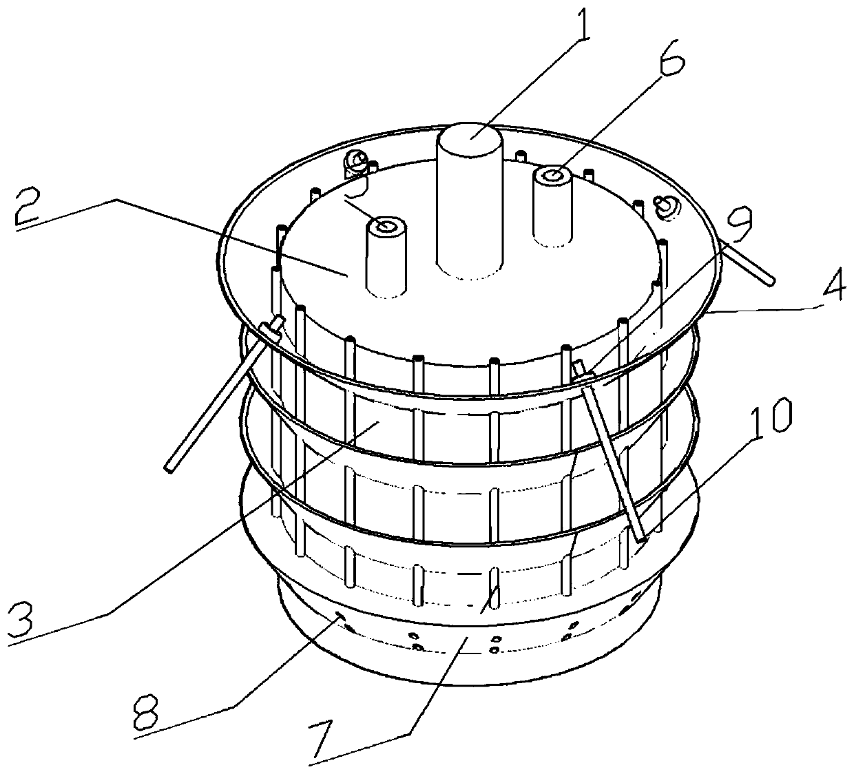
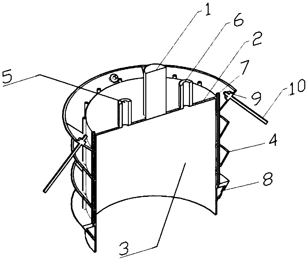
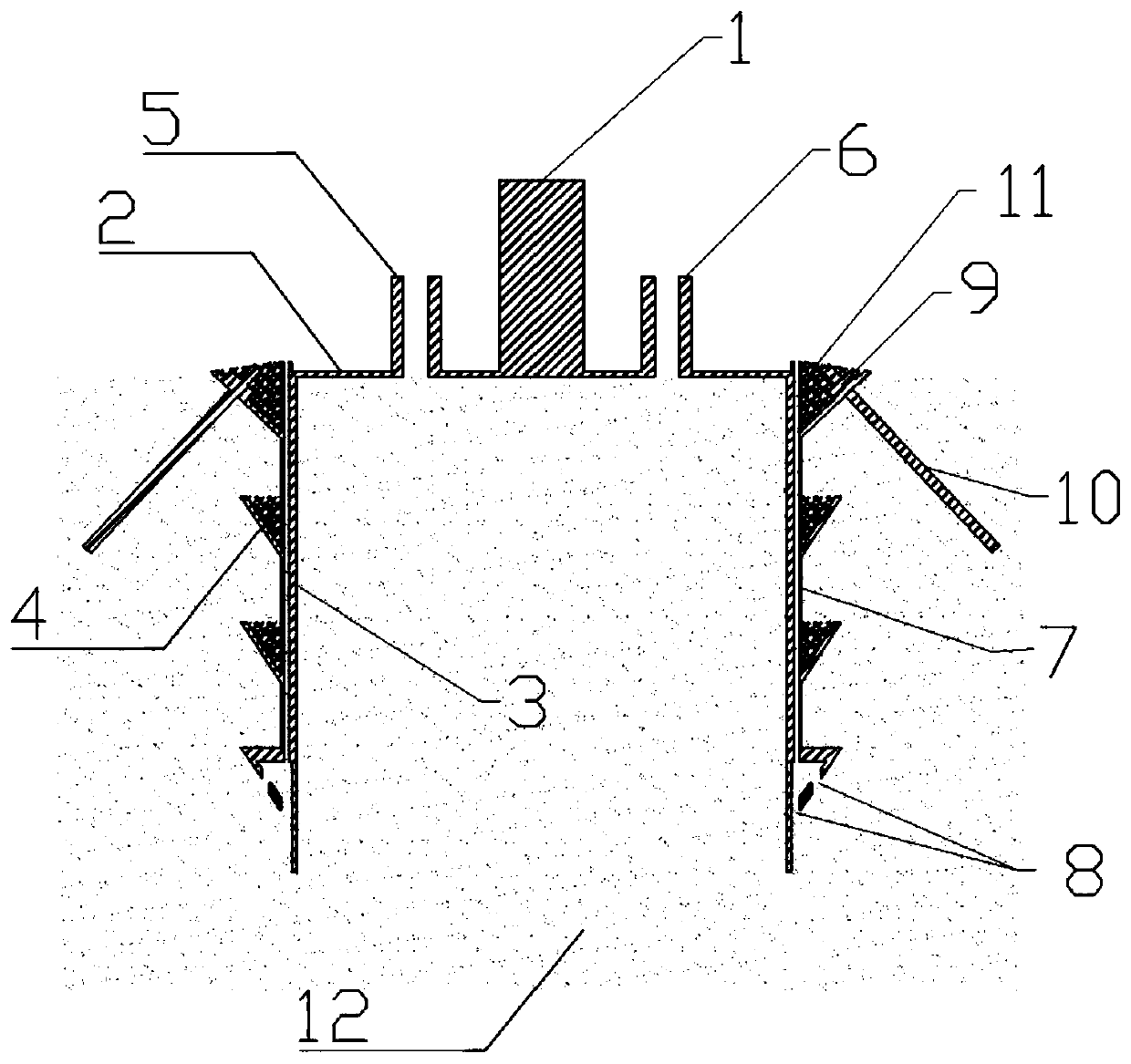
[0028] figure 1 is a three-dimensional structure schematic diagram of the present invention; figure 2 yes figure 1 The longitudinal center plane sectional view of ; image 3 It is a sectional view of the longitudinal central plane of the present invention; Figure 4 yes figure 1 The top view of the top view; the names of the parts marked in the figure are in order: connecting rod 1, barrel cover 2, barrel wall 3, annular chute 4, self-weight pneumatic valve 5, vacuum pump pneumatic valve 6, water pipe 7, water outlet hole 8, anchor plate 9 , self-drilling bolt 10, gravel 11, soil 12.

[0029] It can be seen from the accompanying drawings that the foundation of the anti-pull...


PUM


Abstract

The invention discloses an uplift suction bucket foundation and an installation method thereof. The suction bucket foundation comprises a suction bucket; and a dead weight sinking system, a water flush sinking system, a reinforcing system and a plurality of layers of annular inclined grooves are further arranged on the periphery of the suction bucket. The method comprises the following steps that1, the dead weight of the suction bucket is increased; 2, the suction bucket sinks due to the dead weight; 3, the suction bucket sinks due to a water flush; 4, the suction bucket is reinforced; and 5,the dead weight of the suction bucket is increased again. According to the uplift suction bucket foundation and the installation method thereof, the annular inclined grooves are additionally formed,water conveying pipes penetrating through the annular inclined grooves are additionally arranged, gravel is placed in the annular inclined grooves so that the dead weight can be increased, the dead weight sinking depth can be increased, the water conveying pipes penetrating through the annular inclined grooves output high-pressure water flow so that the suction penetration resistance can be greatly reduced, rapid sinking can be realized, self-drilling anchor rods are arranged on the annular inclined groove at the uppermost layer so that the effect of the suction bucket can be further stabilized, and the uplift bearing capacity of the suction bucket foundation can be greatly improved.

Description

technical field [0001] The invention relates to an anti-pull suction bucket foundation and an installation method thereof, belonging to the technical field of marine suction bucket foundations. Background technique [0002] The suction barrel foundation is a kind of marine foundation, which is often used as the foundation of offshore platforms and offshore wind power. For offshore platform foundations and multi-legged (three-barrel or four-barrel) offshore wind power foundations, under the action of horizontal loads such as sea wind, waves, and ocean currents, the failure mode of the suction bucket foundation on the windward side is pulling failure, and the failure mode of the suction bucket foundation on the leeward side is The mode is vertical compression deformation. Moreover, the uplift bearing capacity of the suction bucket foundation is much smaller than its compressive bearing capacity, so improving the uplift bearing capacity of the suction bucket foundation is a co...

Claims


Application Information

Patent Timeline
Patent Type & Authority Patents(China)
IPC IPC(8): E02D27/52E02D5/74
CPCE02D5/74E02D27/52
Inventor 刘金忠朱珍德王保田陈旭光阙相成张聪龚超何燕新
Owner HOHAI UNIV
Why Eureka
Try Eureka