Shift mechanism, shift system and shift control method of automatic transmission
A technology for shifting motors and controllers, which is applied in the direction of transmission control, mechanical equipment, and components with teeth, etc. It can solve the problems of cumbersome shifting process, complex mechanism structure, and difficult maintenance, so as to maintain performance and improve The effect of compact structure and strong versatility
- Summary
- Abstract
- Description
- Claims
- Application Information
AI Technical Summary
Problems solved by technology
Method used
Image
Examples
Embodiment 1
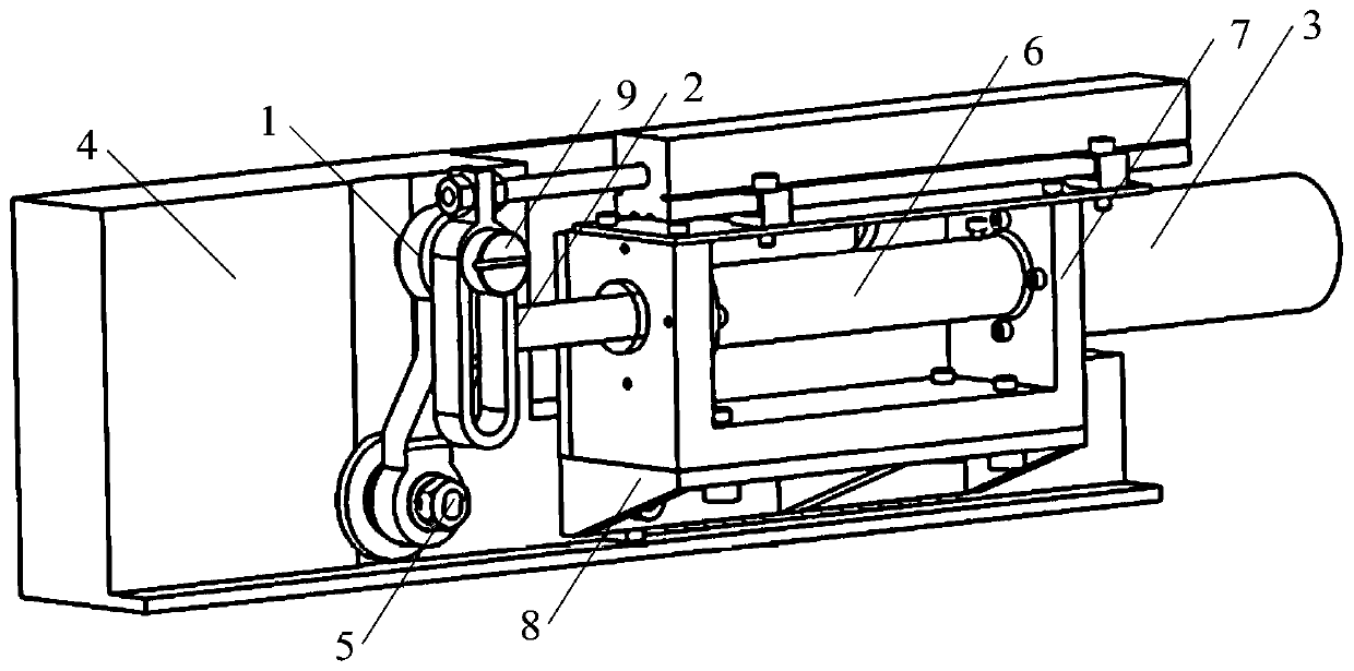
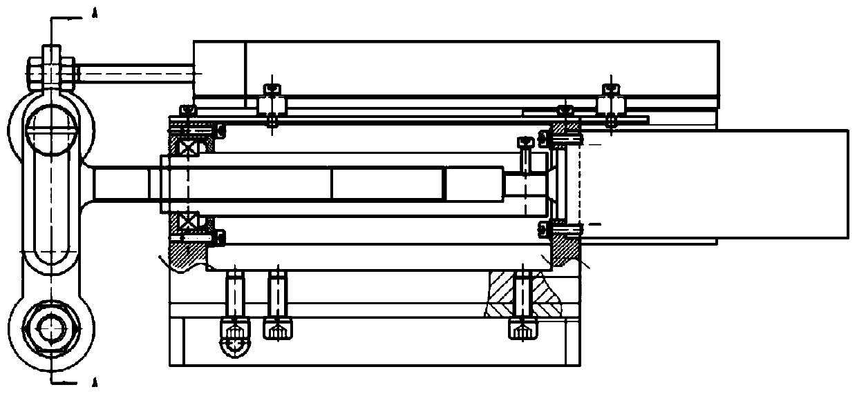
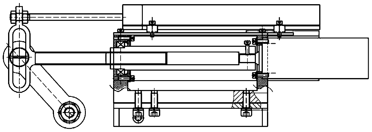
[0046] This embodiment provides a shift mechanism of an automatic transmission, such as Figure 1 to Figure 6 As shown, it includes a shift lever 1, a screw thrust rod 2 and a shift motor 3. Wherein, one end of the shift rod 1 is fixedly connected with the shift shaft 5 on the box body 4 of the automatic transmission, and the other end of the shift rod 1 is inserted into the helical thrust rod 2, and slides up and down in the helical thrust rod 2 ; One end of the helical thrust rod 2 is threadedly connected with the output shaft of the gearshift motor 3, and the rotation of the output shaft of the gearshift motor 3 is converted into the helical thrust rod 2 and moves linearly from side to side through the thread.
[0047] When shifting is required, the shift motor 3 is driven, and the output shaft of the shift motor 3 rotates relative to the helical thrust rod 2, and the number of threads engaged with each other changes, converting the rotational motion of the output shaft of ...
Embodiment 2
[0062] This embodiment provides a shift system, such as Figure 7 As shown, it includes a displacement sensor 11, a shift actuator 12, a shift controller and the shift mechanism provided in Embodiment 1, and the shift actuator 12 includes a vehicle speed comparator. Wherein, the gearshift actuator 12 is electrically connected with the displacement sensor 11, the gearshift controller and the gearshift motor 3 respectively; the gearshift controller sends the desired logical gear position to the gearshift actuator 12; connection, used to obtain the actual position signal of the screw thrust rod 2, and transmit it to the gear shift actuator 12; the gear shift actuator 12 converts the received actual angle value of the screw thrust rod 2 into an actual logical gear value, and the gear shift is executed The device 12 receives the current vehicle speed value, and judges whether the current vehicle speed is 0 through the vehicle speed comparator. The control strategy determines the r...
Embodiment 3
[0069] This embodiment provides a shift control method for a shift system, such as Figure 8 shown, including the following steps:
[0070] Step 1: The shift actuator receives the expected logical gear value sent by the shift controller. Specifically, in the manual driving mode, the gear shift actuator receives the expected logical gear value sent by the driver through the electric control handle; in the automatic driving mode, the gear shift actuator Expected logical gear value;
[0071] The shift actuator obtains the actual position signal of the shift lever collected by the displacement sensor, and obtains the actual logical gear value through analysis.
[0072] Step 2: The gear shift actuator judges whether the expected logical gear value and the actual logical gear value are equal, if they are equal, the gear will not be shifted; if not, then go to step 3;
[0073] Step 3: The shift actuator receives the current vehicle speed signal, and judges whether the current vehi...
PUM
 Abstract
Description
Claims
Application Information
 - R&D
- Intellectual Property
- Life Sciences
- Materials
- Tech Scout
- Unparalleled Data Quality
- Higher Quality Content
- 60% Fewer Hallucinations
Browse by: Latest US Patents, China's latest patents, Technical Efficacy Thesaurus, Application Domain, Technology Topic, Popular Technical Reports.
© 2025 PatSnap. All rights reserved.Legal|Privacy policy|Modern Slavery Act Transparency Statement|Sitemap|About US| Contact US: help@patsnap.com


